Eng-Tips is the largest engineering community on the Internet

Intelligent Work Forums for Engineering Professionals

How to calculate the force necessary to deform a bent sheet metal item

Status
Not open for further replies.

phoenixMetal

Mechanical
Dec 12, 2008
3
0
0
US
I am trying to determine how to calculate the force necessary to permanently deform a certain sheet metal item which has some bends.

Here is an image of the part:
Outside_post_to_rim_joist_connector_-_question_for_engineering_site_rh2ggr.png


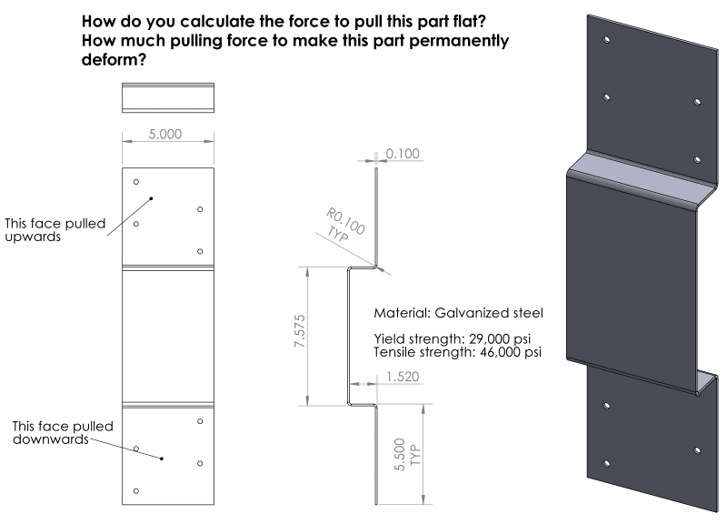
If there was a force that pulled the upper and lower halves apart (pulling in the direction that would flatten out the part if pulled hard enough), I'd like to know how to calculate that force.

I am not just looking to find out the numerical answer for this particular part. I am looking to learn the formula for how this sort of thing can be calculated for any similar part which may have more or less bends, different thickness, etc.

It is OK to assume that the flat areas of the part are perfectly rigid, so that we are talking about the deformation happening only in the bend regions. It is also OK to make any other reasonable shortcuts or simplifications to get a ballpark calculation.

The question could also be framed in any of the following ways - if you can more readily determine how to calculate for any of these scenarios:
1)How to calculate the force needed to permanently deform the part any amount?
2)How to calculate the force needed to deform (pull apart) the item by 0.1 inches (or any other arbitrary amount), with the deformation not necessarily being permanent.
3) How to calculate the force needed to pull the part substantially flat?

Part dimensions and mechanical properties for this example:
Material: Steel sheet
Yield strength: 29,000 psi
Ultimate tensile strength: 46,000 psi
Material thickness: 0.1"
Part width: 5"

Let me know if you have any questions and thank you for your help!
 
Replies continue below

Recommended for you

To do what you are attempting to do ( Which I suspect is hypothetical.) you need to look at the art of stretch bending.
In order to flatten that metal by tensile force, you are going to have to stretch the metal past its yield point, to undo the actions of the bends which stretched the outer portions of the metal, and compressed the inner portions of the bends. So if the theoretical yield of the metal is 29000Psi then you should start at 29500psi and work up.
Here is a link to an old post on stretch forming from 2012: thread2-326225
. If in fact you simply need to adjust the shape to make the part fit something, you would be better off using a flattening die in a press brake and controlling by distance rather than pressure.
B.E.

You are judged not by what you know, but by what you can do.
 
There is a way of designing portal frames and the like using the moment of plasticity of an assumed mechanism in the frame. Then use a work equation such that the force times the distance it moves is the sum of the moment of plasticity of each hinge line times its rotation.

Eyeballing it
1) hinge line at the centre of the 7.575
2) whole different question, just your usual elastic beam analysis.
3) impossible to say until you define substantially flat and the material properties etc.

Cheers

Greg Locock


New here? Try reading these, they might help FAQ731-376
 
In the real world, I'd bend the sheetmetal, screw both flat ends to separate boards, put the boards on a flat (controlled) surface such as a milling machine bed, and pull them apart. Measure the pull and subtract friction.

In the theoretical world you prefer, start by reading the pipe stress handbooks for pipe bends, pipe thermal expansion loops. ALL of the theory is there, but the shape of the metal under stress (both plastic and completely elastic) is different.
 
Hello As mentioned there are better ways to make it flat. But the moment at each bend will be close to 1.5" x the pull force. Once you get to above yield (as mentioned) the part will start to flaten out, but more pull force will be required to maintain the stress above yield. As the 1.5" gets smaller. Actually 1.5" is always 1.5", but I think you get the meaning.

The stress at joint will be about (moment at the bend)/(section modulus of sheet). S=1/6 x (Thickness squared) x width.

Roarke's book on stress and strain has quite a few frame cases that could be a check on the initial aproximations.
 
Once you go past the point where the tensile force exceeds the yield stress of the material across the entire cross section, so that the entire part yields, It will be flat and stay flat.
 
If the two bolted faces can be assumed staying planar completely up to the bends towards the 1.52 long face and moving apart each in line, then the answer to question 2 can be found using elastic beam analysis.
Since the part is symmetric I suggest to do such analysis only on the top half and then double the z deflection.
I found for the z deflection of the total piece the following relation between force and deflection: F.L^3/(3.E.I) whereby L = 1.52"
This result is interesting since it is also the well known formula for cantilever beams;-)
But that's only the answer for question 2 assuming to stay in the elastic zone.
 
PhoenixMetal:
I basically agree with GregLocock’s post of 16JAN19, 9:47, except I don’t think you will get the bent piece perfectly flat or wrinkle free. At the original four bends, you have taken the piece well beyond yield strength and deformation on the material stress/strain curve, and this is something you can’t undo. Fy and Fu might be higher than the ASTM Std. min. values and you have to know those values and the shape of the stress/strain curve. The material may now be working in its strain hardening range which starts to change the stress/strain curve w.r.t. further stressings and strains. In any case, you will have to pull the piece very uniformly, so as to move the stresses and strains beyond the old max. points on the curve to try to straighten out the old bends, further stretch the whole piece. And, the old bend areas may react slightly differently than the virgin material away from the bends. That is, the straightening force/stress (straight pulling, not bending over a die, which may react differently) will have to be higher than the original bending stress. And, you may still have to apply some perpendicular pressure to the original bend areas. These kinds of problems usually involve some testing to reach a final conclusion, and are probably not worth it for a few pieces.
 
My question is what is the OP going to do with the part after he has stretch straightened it ? In order for it to be flat he has to go to at least first yield on the part, point c on the attached diagram. This will of course stretch the part to where all of the hole dimensions will change. Then if the part has to be re bent, the existing dimensions for the holes will be useless.
B.E.


You are judged not by what you know, but by what you can do.
 
1) draw a FBD of 1/2 the plate (based on the symmetry); so now you have a "Zed" shape.

2) when you load the plate in tension, the "bent" portion will deflect towards the loading plane.

3) so you should be able to draw how the "Zed" deflects.

4) to point is that there's a lot of bending of thin sheets happening. Initially M = P*h, stress = 6M/Wt^2.

5) this will not deflect and stay "flat" to any meaningful definition of "flat". The initial bends will keep alot of their shape so "flat" may be the center deflects to the same plane as the ends (and say nothing about the position of the rest of the shape). Even this is unlikely given spring back, when the load is removed.

another day in paradise, or is paradise one day closer ?
 
rb1957, keep on stretching that strip after it is straight so that the whole cross-section of the strip, along its entire length, yields. After that the whole strip will be flat, and stay flat. Same with a wire that has bends in it.
 
force needed to pull the part substantially flat is easy since the closer to flat it gets the more like a tensile test specimen it becomes

First order approximation is Fty x cross sectional area
noting that fty will be effected by the level of cold working in the bends
 
If you are trying to estimate this in any way using principles of flat plate bending, know that the typical relation for bending stress 6M/bt^2 will inherently not hold since the intention or requirement is to plastically deform the sheet again.

For that you will need to consider some type of plasticity correction which is not so simple for a flat plate as with a prismatic beam.

Keep em' Flying
//Fight Corrosion!
 
Status
Not open for further replies.
Back
Top