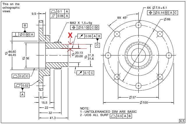
In order to calculate X min. do I need to use the profile tolerance from the general note?
Profile|0.5|A|B| is a location control, but runout isn't (as previously discussed below).
What do you think? Which FCF should I use to get the correct min. wall?
That is what I get from Evan's replay:
"gabimot,
Short answer - total runout does not control the radial location of the surface (assuming that I understand what you mean by "radial location").
One problem here, that Y14.5 perpetuates, is the use of terms such as "location" to describe what is being controlled. As we have found in this thread, the terms "radial location", "axial location", and "surface location" may mean different things to different people.
I have found it very useful to describe constraint in terms of the transformations that are allowed and not allowed. So I would describe a Total Runout tolerance zone in the following way:
-The tolerance zone has perfect form.
-The zone cannot rotate relative to the datums
-The zone cannot translate relative to the datums
-The zone can "progress" (that is, offset away from the nominal surface while keeping the distance between the two boundaries constant)
So the Total Runout tolerance zone in your Surface_location example is two coaxial cylinders 0.02 apart, that are perfectly coaxial to datum axis A. The zone cannot translate or rotate relative to datum axis A. But the zone can progress (the diameter of the two coaxial cylinders is variable - they just have to maintain the radial distance of 0.02). This property is what makes the Total Runout zone not control size. This would be controlled by the 7.780 +.025 -.012 size tolerance.
Evan Janeshewski
Axymetrix Quality Engineering Inc.
www.axymetrix.ca"

