Continue to Site

Eng-Tips is the largest engineering community on the Internet

Intelligent Work Forums for Engineering Professionals

  • Congratulations KootK on being selected by the Eng-Tips community for having the most helpful posts in the forums last week. Way to Go!

HOW TO CONSIDER THE STATIC HEAD IN A BRANCHED PIPE 1

Status
Not open for further replies.

CHK07

Mechanical
Jan 30, 2023
12
I was doing the head loss calculation for my swimming pool system for sizing suitable pump for filtration. Here I can use a maximum of 4" pipe. I calculated thr head requirement for my system. Here I have 7m static head and the friction losses around 13m. But I need to reduce the friction loss without increasing the pipe size.
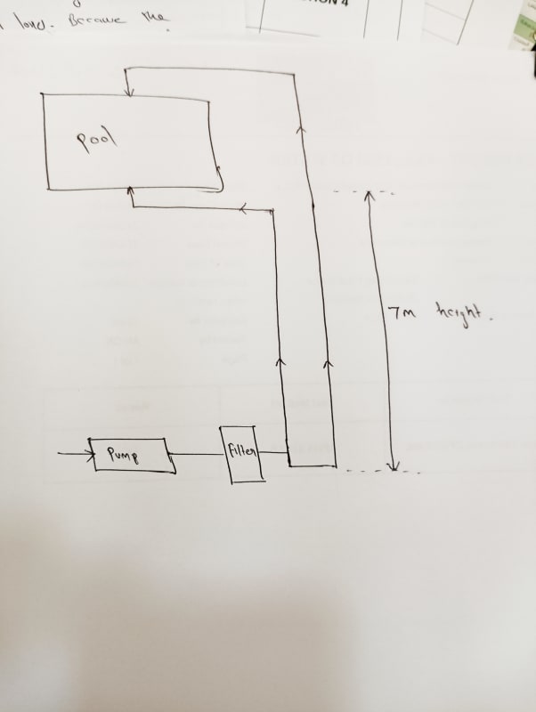
If I add one more branch, I can reduce friction loss. Because the flow rate required should be reduced to half. But if I do so, how can I take the static head?. Is it 7m or do I need to consider it as 14m? Because 2 pipes are running vertically. Pls check the attachment.
 
Replies continue below

Recommended for you

1) no attachment
2, if this is a recirculation pump there should be no static head relevant as in a closed loop system the two heads in the flow and return leg cancel each other out. but please include a diagram.
3) usually there is a filter which has a variable head loss as it get clogged - is this what you mean by a static head?

Remember - More details = better answers
Also: If you get a response it's polite to respond to it.
 
Thanks for your rply

Actually I have an over flow pool, where the overflowing water is falling to the tank through gravity. The tank is located in the pump room. So from the pump room I need to pump the water to the pool which is located 2 floor above ( 7m heigh) for making the pool overflow. I mentioned the static head as the 7m height, that is the vertical distance between water level in the tank and pool. I have a friction loss of 13m by considering all the pipe loss and minor losses including filter.
I thought, If I divert the pipe that going to the pool ( after filter ) into 2, I could've reduced the friction loss. But the vertical height that is 7m. TDH = friction loss + static head. So if I add 2 pipe, how can I take the static head. Is it 7m or 14 m..
 
 https://files.engineering.com/getfile.aspx?folder=05409337-3160-42d4-87c4-2fabb5bbbe93&file=IMG_20240514_123118.jpg
What you need is the height from the water level in the tank ot the highest point of your pipe, if the outflow from the pipe is above the water level or the water level in the pool if your pipe connects into the pool below water level.

That static lift is the same if you have one pipe or 10 pipes.

If your flow is the same and you simply duplicate the pipes the same size, then your pressure drop from friction (not including the filter) will drop by a factor of 4. (half the velocity and friction is prop to velocity squared).

Getting absolute equal flow is next to impossible, but you won't be far away. Just recombine the tow pipes just before exit into the pool.

Your sketch is a bit basic so I'm not sure if one pipe is longer or goes to a different place as you haven't shown water level. If one pipe is even a bit longer or has more bends or is higher than the other then flow could be 75:25 if you're not careful.

Can yo draw a more exact one? with true levels and lengths? ANd the full system including return line to the tank?

Picture here as supplied

IMG_20240514_123118_vk9i9w.jpg


Remember - More details = better answers
Also: If you get a response it's polite to respond to it.
 
Static head remains at 7m.

Friction head drops by more than half, as friction is squared with velocity.
Looping the system by adding another equal diameter pipe halves the velocity.
Friction can drop to 1/4th that of a single pipe.

Initial Friction = k x V^2
Halving the velocity, Friction = k x (V/2)^2
Friction = (k x V^2)/4

--Einstein gave the same test to students every year. When asked why he would do something like that, "Because the answers had changed."
 
Had to make a coffee before posting, so that now just confirms LI answer.

--Einstein gave the same test to students every year. When asked why he would do something like that, "Because the answers had changed."
 
Thanks for your rplys..

Now I understood.
Is there any issue for connecting pipes larger than the pump connection on the pump by reducing on the pump area.
Because here I use 4" pipes. Can I connect a centrifugal pump having 2" connections on this 4" pipe? Is there any issue for that
 
No issue.

Generally pool pumps are pretty robust and it is all about matching the pump curve (head vs [EDIT] flow pressure) to the system curve of static head + friction vs flow to make sure you are in the right zone. Too little flow and your pump is churning away not doing much. Too little back pressure and the flow is too high.

But these small pumps really don't mind too much. Just make sure the head is more than 7m...

Remember - More details = better answers
Also: If you get a response it's polite to respond to it.
 
7m plus suction line head loss, if any. Give yourself a little margin there as necessary.

--Einstein gave the same test to students every year. When asked why he would do something like that, "Because the answers had changed."
 
Hii. Thanks alot for the rplys

I did the calculation for the system. Pls take a look on the attachment. Is it the right way..?

Also,
How can we find the pressure on each area of the system.. For example, I have the filter which have a maximum capacity of 4bar pressure. How can I find the pressure at the filter area when the system is working..?
Also how to find the pressure at an portion before the pump while working..
 
 https://files.engineering.com/getfile.aspx?folder=bdd686f3-4324-485e-bb84-abade67bd594&file=For_eng_tips.pdf
Looks pretty close.

The common parts are at 56 m3/hr, not 28.

Filters have a range of head loss depending on fouling. You need to measure differential pressure to know when to replace the filter, but it might start at 2.5m headloss and go to maybe 7.5 or higher?

Guages are your eyes.

Remember - More details = better answers
Also: If you get a response it's polite to respond to it.
 
Thankyou Littleinch.
Is there any way for finding the pressure ( gauge pressure ) in the filter theoretically...?
Is there any formula for finding it..?

Not only for the filter I'm asking generally.
Here by positioning a perticular pump, we can predict the result flow through the system..
But shall we know the pressure at a perticular portion of the system theoretically..? Is there any way for that..
 
Filters are a law unto themselves, but the whole purpose of a filter is to errr filter. As time goes on this increases DP across them. Typically vendors allow up to 0.5 to maybe 1 bar DP before the filter becomes too clogged and is in danger of bursting or breaking. Each filter type will have a min and max DP for clean and dirty- you just need to read the vendor literature carefully and put in guages so you know when to clean or replace the filter. You don't want to be changing it based on a time event which might be too short or too long. Over time you will get to know how often they need changing.

But yes, you start at one elevation and start point of the pump discharge, then subtract the static head difference and the frictional losses and you have your head/pressure at any particular point. Pressures will change depending on the DP of your filter. Higher flow when clean, lower flow but prob higher pump head when dirty.

Remember - More details = better answers
Also: If you get a response it's polite to respond to it.
 
Status
Not open for further replies.

Part and Inventory Search

Sponsor