Continue to Site

Eng-Tips is the largest engineering community on the Internet

Intelligent Work Forums for Engineering Professionals

  • Congratulations waross on being selected by the Eng-Tips community for having the most helpful posts in the forums last week. Way to Go!

how to create meshed shell/surface created by three half circles 2

ITsSB

Structural
May 6, 2022
30
I don't know if this belongs here but,
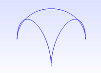
I want to create a shell structure created by three half circles vertically rotated at 60°. (see attached image). So, is there any easy way/tool to create this meshed shell? (I will use it elsewhere for complete structural analysis.) So far I have tried using GMSH but couldn't generate the mesh/surface.Screenshot 2024-11-12 155833.png
 
Last edited:
Replies continue below

Recommended for you

what preprocessing code are you using?
suggest deleting this post and reposting in the specific forum for the code.
and the mesh at the points in going to be a problem.
 
the surface is spherical, yes? mesh the sphere then cut it.

better embed the edges into the spherical surface and mesh that (so that your edges are part of the mesh.

How you create the spherical surface will affect the resulting mesh !
 
I mean, I agree with rb1957 to a point...but the real question is what the surface you are cutting looks like. You could dip a wire frame made of the 3 half-circles into a soap solution: the resulting bubble film would be a minimum-area surface, and I'm pretty sure it won't be a spherical surface. Similarly, you could drape fabric over the frame, and the tension/tent surface formed would be something other than spherical. The sharp corners are going to be problematic for anything real, but we haven't got there yet.
 
or is it the intersection of three cylinders ?
or maybe is there a triangle on the top ??
 
or is it the intersection of three cylinders ?
or maybe is there a triangle on the top ??
No its not. Originally, those three circles were ellipses. (the major and minor radius of the ellipse are nearly identical that's why I wanted to simplify). I'm a Structural Engineer and this shape is given to us from the Architects. Those three Ellipses represent a support structure (beam) and the dome shaped shell/surface created by them represents a roof. We don't usually deal with this kinds of shapes and that's why I wanted to post it in this group. (I kind of think you guys are better in dealing/meshing/creating complex shapes than us.)
 
Last edited:
I mean, I agree with rb1957 to a point...but the real question is what the surface you are cutting looks like. You could dip a wire frame made of the 3 half-circles into a soap solution: the resulting bubble film would be a minimum-area surface, and I'm pretty sure it won't be a spherical surface. Similarly, you could drape fabric over the frame, and the tension/tent surface formed would be something other than spherical. The sharp corners are going to be problematic for anything real, but we haven't got there yet.
Yes, I couldn't do that for the same reason you said. The next question will be how to create that curved surface( the part to be removed) as it is, in which I don't know how to do that. Even after that I don't think I could have all the meshes have a node at the curved edge in which I have a beam there for a proper load transfer.
 
what will the skin look like between the arcs ? flat ? curved (outwards or inwards) ?

maybe take a triangle, supported at the three corners, and apply a load to the center (discrete or distributed), and allow the triangle to deform hyper-elastically ... just to see the shape it becomes ?

then the question becomes "how are you going to make this ?" how do they make tension surfaces ? I imagine they have a near nett shape surface cut, and then installed with a (small?) tension force, with a bit of finessing (ie farting around) to remove any wrinkles ??

But this shape isn't a tension surface, is it ?? or are the "rings" supporting the edges (and the surface) ? I think the shape can be anything you want it to be (flat, curved, dished). I suspect that the three legs are more naturally dished, but that becomes harder to make and to model. Is the surface a tension surface or free standing ??
 
You described the surface/roof as a "dome", which implies it has a spherical contour. So, try rb's suggestion of starting with a half-sphere and cutting the 3 arches through the surface.

edit: dunno why you are posting this question (which sounds like a structural/CivE problem given you are dealing with architects?) in an aerospace forum more suited to rockets and spacecraft, &/or possibly airplanes.

edit2 - just read rb1957's post this morning, and agree that it would be cool to pin the corners of a triangle and play with different loadings on a hyperelastic mesh to see what surfaces develop (maybe some kind of hyperboloid?).
 
Last edited:
It's a bit slow this morning, so generated these. File dome shows the result of starting from a hemisphere and piercing it with 3 arches. The pipe join files show the result(s) of intersecting 3 half-cylinders, with two ways of terminating the surface.
 

Attachments

  • DOME.pdf
    27.6 KB · Views: 9
  • pipejoin1.pdf
    30.5 KB · Views: 6
  • pipejoin2.pdf
    25.2 KB · Views: 5
and....crickets.
Sorry I know its disrespectful to ask a question and be silent. I apologize but I didn't know how to respond.
1. The top level of my so called "dome" and the half circle are at the same elevation so if i try to cut the sphere with the curve (beams) all of the top surface will be removed (for obvious reason).

At this point I don't think that central part can be mathematically be represented. I made an approximation by making the diameter of the circle a bit lower as you suggested and got over it now. Although I submitted the project, I was going to try a few other options and get back to you guys but I really couldn't and I apologize. I really appreciate the help I got from all of you especially from yours. Thank you.
 
the thing is you can't define a surface by those three arcs. What happens between the arcs ? are they three cylindrical surfaces, intersecting at a hard boundary ? Is the shape a spherical dome with cut-outs ? Is there a radius along the intersection lines (of the three cylinders) ? Is the surface flat between the arcs, like I imagine it would be if material was tensioned over the arcs ?? Does it bow inwardly (which is natural if there is slightly too much material) ??
 
the thing is you can't define a surface by those three arcs. What happens between the arcs ? are they three cylindrical surfaces, intersecting at a hard boundary ? Is the shape a spherical dome with cut-outs ? Is there a radius along the intersection lines (of the three cylinders) ? Is the surface flat between the arcs, like I imagine it would be if material was tensioned over the arcs ?? Does it bow inwardly (which is natural if there is slightly too much material) ??
the top surface is a tensioned surface between the arcs and the lower part is a curved downward dome . I don't have a parameter for the curved part. (other than the radius of the projected curves (the two arcs at 60°). But I will have a smooth transition between these two. (a fitting curve here)
In reality, simply put, three arc supports and tension a thin surface between these supports. A curve fitted between these three arcs, thats what am looking for.
Edit: I appreciate all of you guys and no longer need this. Thank you all.
 
Last edited:

Part and Inventory Search

Sponsor