Continue to Site

Eng-Tips is the largest engineering community on the Internet

Intelligent Work Forums for Engineering Professionals

  • Congratulations KootK on being selected by the Eng-Tips community for having the most helpful posts in the forums last week. Way to Go!

How to create points from Excel data (designtable) to make CAM profile

Status
Not open for further replies.

wadd3456

Mechanical
Apr 28, 2010
2
I have a table of x,y coordinates in Excel and have imported them in as a design table. How do I make Catia create 2d (or 3d) points using this data?

Ultimately these hundreds of points will create a CAM profile.

Thanks!
 
Replies continue below

Recommended for you

I'd have to knock the dust off of it, but I have a macro that will modify control points of an existing spline..but it won't create a new spline.

I could send you that and a sample file with an existing spline with 360 points.

The macro works off of angle and length instead of XY coordinates.
 
Last night we found a macro to insert points referencing an excel spreadsheet. Pretty neat stuff. I't still be interested to see what you've whipped up.
 
I assume the method of importing points from an Excel file into V5 is still available; search the online Documentation for "Creating Elements from an External File" — it gives an explanation of how to create points, curves and simple surfaces from a file of X,Y & Z data. Search the Help Documentation for "Creating Elements from an External File"

Here is an extract from the beginning of that Help information:—
"Creating Elements from an External File
You can create points, curves, and multi-sections surfaces from a Microsoft Excel spreadsheet containing macros, and in which you define:
the points space coordinates
the points through which the curves pass
the curves used as profiles for the multi-sections surface."

EquaCurve_06.jpg


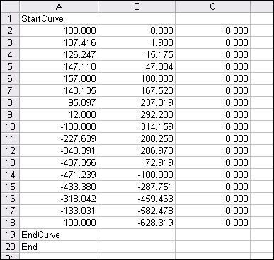
The picture above shows the format of an Excel file to create a spline in V5; even if the points are on the X-Y plane the Z value must still be defined as zero. The software will not work if there is the slightest error in the format of the file; if only X & Y values are used then the job will fail; there must be a value in the third column, even if it is 0.000. The Excel macro that invokes the operation is called "Feuil1.Main"; and the you enter 1,2 or 3 depending on what is to be created: 1 for points, 2 for a spline, 3 for a multi-sections surface (it used to be called a Loft) — and Run. Switch back to Catia — and if the Excel file is properly put together then the elements will be in the Part model.

As far as I can remember the maximum number of points that can be used for one element is 500. If only points are being created then the "StartCurve" and "EndCurve" statements can be omitted — but of course, the file must finish with "End".

I used this method from early 2003 until I retired; it was in V5 from Release 9 onwards, and I never had any trouble with it, but as with most things in Catia, you must stick to the rules . . .
 
Status
Not open for further replies.

Part and Inventory Search

Sponsor