Eng-Tips is the largest engineering community on the Internet

Intelligent Work Forums for Engineering Professionals

  • Congratulations waross on being selected by the Tek-Tips community for having the most helpful posts in the forums last week. Way to Go!

How to Create the 3D solid model( as shown in the image) with different extrusion depths ? 1

Status
Not open for further replies.
Dec 6, 2017
5
0
0
DE
Hello,
I am a Beginner in abaqus and
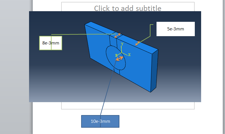
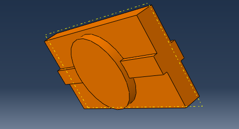
I am trying to create a 3D solid model with different extrusion depths(perpendicular to screen) as shown in the image . The way I was trying to do is:
I created a rectangular solid by extrusion depth of 5e-3mm . And then, I split the central cyclinder with a radius of 2.25mm. But I need the central cyclindrical part only to be of extrusion depth of 10e-3mm and the rest be of 5e-3mm. How can I achieve two cells of different extrusion depth in 3D solid Model?
Thanks in advance
 
 http://files.engineering.com/getfile.aspx?folder=713ec5d0-6920-4245-a6d2-b5ece3d5407e&file=1.PNG
Replies continue below

Recommended for you

I don't understand the problem. In the part module are extrude and cut operation with a sketch as basis. So start one of those, sketch the circle and define the value for the cut or extrude depth. Afterwards you can partition to have multiple cells in that part (if needed).
 
Thank you for your kind response. Sir actually i am trying to create a 3d solid model of a speaker membrane .
3_ijeyro.png


See the newly attached imgae. The central cyclindral part is a copper and the rest rectangualr part is a membrane supporting the thiscopper piece. And also u can see 2 small rectangular ribs attached to cyclinder part . Now as shown in the imgae. I want different depths /thickness for each of this as clearly shown in the newly attached image
 
That looks quite simple. There are several ways to do it. You could sketch and extrude the whole plate first with the smallest height and then add with two mode sketch+extrude the two higher regions. Or you extrude the full block first and then use sketch+cut to remove the material get lower regions.
Overall it is very similar to methods that CAD systems have.
 
Learning Abaqus is something you have to do for your own. Read the "Getting Started with Abaqus" in the manuals. There are also the basics of Abaqus/CAE explained. Then there is the example "Connection Lug" in the section regarding continuum elements, where a simple solid body is created at the beginning with a sketch and an extrusion.
 
Thank you so much Sir, I could get it and create my model . Now I was trying to do the python script for the same . This is the code

from abaqus import*
from abaqusConstants import*
import regionToolset

#Create the Model

myModel=mdb.Model(name='Frequency_analysis_Model')

#Sketching the profile of the membrane

import sketch
import part
x_neg= -5.0
y_neg= -2.5
x_pos =5.0
y_pos =2.5
diameter_of_copper_mount = 4.5
radius_of_copper_mount = diameter_of_copper_mount /2

mySketch=myModel.ConstrainedSketch(name='Paralyene_membrane_sketch', sheetSize=200)
mySketch.rectangle(point1=(x_neg,y_neg),point2=(x_pos,y_pos))

#Creating the 3D deormable part by extruding the created Sketch
extrusion_depth=2.0
myPart= myModel.Part(dimensionality=THREE_D, name='Paralyene_membrane_part', type=DEFORMABLE_BODY)
myPart.BaseSolidExtrude(sketch=mySketch,depth=extrusion_depth)

#Partioning the face
face_point=(0.0,0.0,extrusion_depth)
edge_point=(x_pos,0.0,extrusion_depth)
face_to_be_partioned = myPart.faces.findAt((face_point,))
edge_forpartition=myPart.edges.findAt((edge_point,))

#transformation from sketch coordinates to part coordinates.
Tranformed= myPart.MakeSketchTransform(sketchPlane=face_to_be_partioned)

I am getting error for this below code of line as invalid sketch plane. [I am trying to parametrize my model.so as using only findat method].

Tranformed= myPart.MakeSketchTransform(sketchPlane=face_to_be_partioned)


Thank you so much

 
The findAt() returns you a list. Just add [0] to get the first (and only) entry of that list.

Use print to get information on whats going on.
print face_to_be_partioned
 
Thank you so much sir. Now I am trying to mesh this part as shown in the image
Capture_b9u1zf.png


This is the python code for meshing the part
#Create Mesh
import mesh


elementtype =mesh.ElemType(elemCode=C3D8R,elemLibrary=STANDARD,kinematicSplit=AVERAGE_STRAIN,secondOrderAccuracy=OFF,hourglassControl=DEFAULT,distortionControl=DEFAULT)

all_cells=myPart.cells
mesh_region=(all_cells,)
myPart.setElementType(regions=mesh_region,elemTypes=((elementtype,))
myPart.seedPart(size=1.0,deviationFactor=0.1)
myPart.generateMesh()


But it shows error as syntax error for the line --------------- myPart.seedPart(size=1.0,deviationFactor=0.1)


Thank you
 
A more serious problem is that Abaqus will fail to mesh that part with the current settings, as indicated by the orange color. In order to produce a mesh of sufficient quality you will need to do some careful and clever partitioning (which is difficult but doable with python), or use tets.
 
Status
Not open for further replies.
Back
Top