Continue to Site

Eng-Tips is the largest engineering community on the Internet

Intelligent Work Forums for Engineering Professionals

  • Congratulations KootK on being selected by the Eng-Tips community for having the most helpful posts in the forums last week. Way to Go!

How to determine the Vector?

Status
Not open for further replies.

okan.00

Student
Jan 23, 2024
9
I don´t get how to determine the vector r(AB). I know that i have to transmit the given angels. Please help me guys.


The Solution is r(AB) = (-√3*a,a,0)


Task:
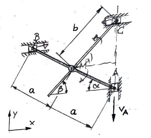
A rod 1 becomes vertical at its end A and at its
End B guided horizontally. In the middle M is a second one
Rod 2 is rotatably mounted, the end C of which is also horizontal
to be led. Point A moves at the constant speed
especially downwards.
a) Determine the velocities of points B and
C

​Given: a, b, α =30°, β =45°, VA=const.
 
 https://files.engineering.com/getfile.aspx?folder=e1ac88bc-0f6c-4021-b1f8-0366e4239aef&file=Unbenannt.jpg
Replies continue below

Recommended for you

wow ! a lot of translation happened ! thx for posting the pic ... the words made little sense !? (but that's is understandable)

Have you "scribbled" an alpha near the upper right corner of M ? I don't think that is right. I think that angle is beta, and the angle between Ab and the horizontal is alpha.

From geometry, cos(beta) = (a*cos(alpha))/b = a/b*cos(alpha)
But I'm not sure what "r(AB)" means as a vector ? it isn't AB (the rod, AB). if it is the rotation of the rod AB ... then describing this as a vector is, to my way of thinking, "odd".

Your second pic, has beta incorrectly placed. This angle needs to be (90-alpha).
I'm not sure the the track B moves in is perpendicular to track A (which seems to be vertical). No, your problem statement has B moving horizontally, and A vertically.
I would look at the triangle AMC, one side length a, another (the hypotenuse) b, leaving AC as ?, angle MAC (90-alpha), angle AMC is (alpha+beta), angle MCA is (90-beta).

"Hoffen wir mal, dass alles gut geht !"
General Paulus, Nov 1942, outside Stalingrad after the launch of Operation Uranus.
 
okan said:
BA[/color]]I don´t get how to determine the vector r(AB). I know that i have to transmit the given angels. they're not angels...they're angles.
Please help me guys.

The Solution is r(AB) = (-√3*a,a,0) What is r(AB)? Are you defining a 3D vector, i, j, k? Your sketch appears to be 2D.


Task:
A rod 1 becomes vertical (it can't become vertical unless b=a) at its end A and at its
End B guided horizontally. In the middle M is a second one (a second what?)
Rod 2 is rotatably mounted (does that mean the two rods are pinned at M?), the end C of which is also horizontal
to be led. Point A moves at the constant speed
especially downwards. (No it doesn't. The mechanism will bind.)
a) Determine the velocities of points B and
C (Are you claiming that point C is moving?)

​Given: a, b, α =30°, β =45°, VA=const.
Your verbal explanation of the problem is terrible and your sketches are even worse.
 
okan.00 said:
The Solution is r(AB) = (-√3*a,a,0)
In a 2D system, vector AB = (i, j) where i and j are the X and Y components of the vector AB. So vector AB = (-2a.cos30, 2a.sin30) or (-√3*a,a)

I first thought the two rods were pinned together at point M, which would mean the mechanism would bind, but if Rod 2 passes through a ring attached to Rod 1 as it appears below, Rod 2 has no effect on the movement of Rod 1.

Capture_ivt5me.jpg


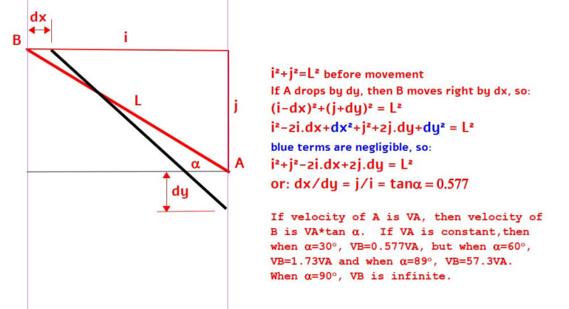
If A drops dy and B moves right dx, we should be able to find the relative velocity of B in terms of A's velocity.

Capture_fyrorq.jpg


Point C is stationary, so its velocity is zero.

And that is the end!
 
"So vector AB = (-2a.cos30, 2a.sin30) or (-√3*a,a)" ... for an origin at A.
"Point C is stationary, so its velocity is zero." ... no, I don't think you can conclude this. M is the midpoint of AB, and CM is a constant "b", and C is constrained to move horizontally.
I think this'll limit the movement of AB.

We know the co-ords of M (-sqrt(3)/2*a, a/2) ... for an origin at A. We can deduce the co-ords of C (length CM = b, angle 45deg) Pictorially C looks to be above A; but "b" is "given" ... ?
if b = sqrt(2)*a (then C will be directly above A).

A, M, B, C could de co-linear (at some deformation)

"Hoffen wir mal, dass alles gut geht !"
General Paulus, Nov 1942, outside Stalingrad after the launch of Operation Uranus.
 
rb1957 said:
"So vector AB = (-2a.cos30, 2a.sin30) or (-√3*a,a)" ... for an origin at A.

It goes without saying that the origin of Vector AB is A. By the same token, Vector BA is (2a.cos30, -2a.sin30) or (√3*a,-a) and the origin is at B.

rb1957 said:
"Point C is stationary, so its velocity is zero." ... no, I don't think you can conclude this. M is the midpoint of AB, and CM is a constant "b", and C is constrained to move horizontally.
I think this'll limit the movement of AB.

I would agree with you if CM is pin connected to AB at M. That was my original understanding, but I now believe that CM is loosely connected to AB by passing through a ring which is part of AB.

If so, CM cannot limit the movement of AB. If not, i.e. if AB is pin connected to CM at M, the assembly can't work. It would simply bind.
 
to me M is a rotational joint on AB, and MC is a fixed length, but thinking about it some more, MC doesn't affect the motion of AB, if b > a.

with the origin at the current location of A, B moves along a line at Yb = a between -2a < Xb < 0, and Xa = 0 (A moves vertically through the origin) between a > Ya > -a.
Coincident with these extreme positions M moves from (-a,a) and (0,0) ... in a straight line ?

I think the way you determined the motion was very insightful.

"Hoffen wir mal, dass alles gut geht !"
General Paulus, Nov 1942, outside Stalingrad after the launch of Operation Uranus.
 
Soryy guys english is not my first language. This was really helpful and i appreciate that.
 
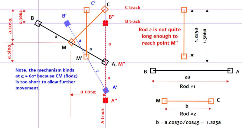
Rotations of AB (Rod#1) at 30, 60 and 90 degrees are shown in black, blue and red. CM (Rod #2) is shown in orange. I believe rb1957 was correct in assuming that the two rods are pin connected at M (not inserted through a ring as I supposed). If the angle beta is 45[sup]o[/sup], length of CM = b is not quite long enough to reach point M in the 90 degree position, which means that the initial angle should be modified.

So far as I can see, my earlier calculation of VB seems correct, but it somehow doesn't seem right that point B would be moving so fast at the end of the trip. I no longer believe that VC is zero, but I have not completed that calculation pending a change in the angle beta.

Capture_tkrlg7.jpg
 
okan.00 said:
Soryy guys english is not my first language. This was really helpful and i appreciate that.

Not a problem, but there is still a problem with the geometry. If the two rods are pinned at M, then Rod #1 (AB) can't continue past an angle of alpha = 60[sup]o[/sup]. It is stopped in its tracks by Rod #2 (CM) which is too short to allow it to continue to the final position where alpha = 90[sup]o[/sup].
 
this is based on the assumption (quite warranted) that C is directly above A.

We are told "b is given" and then not given a value, so we calculate a value based on an interpretation of the sketch.
We "could" start from the vertical " position, and for different b values (since the position of C is determined only by b) see if we can backtrack to the problem position.

Unless I'm mistaken, BA has determined b based on the starting geometry and C being above A. Thus assumptions positioned the track that C runs in.
What I mean is if b was 1.366a, so that the final " position could be achieved, then the original position couldn't be (beta would not be 45deg).
If b = 1.366a and beta = 45 deg, then C would be higher, probably not above A and further from A, and the final " position would (probably) not be achievable.

"Hoffen wir mal, dass alles gut geht !"
General Paulus, Nov 1942, outside Stalingrad after the launch of Operation Uranus.
 
rb1957 said:
Unless I'm mistaken, BA has determined b based on the starting geometry and C being above A. Thus assumptions positioned the track that C runs in.

That is correct; it's what the original sketch indicated.
 
It may be concluded that Rod #2, CM has no effect on the movement of Rod #1, AB unless it is too short, preventing point A from moving to its correct position.

If CM is longer than required, it just moves along C track, and AB is free to find its correct orientation.

The locus of point M can be found by taking the average X and Y co-ordinate of A and B for any angle alpha. Point M will have both X and Y co-ordinates, except when alpha is 90[sup]o[/sup].
 
Status
Not open for further replies.

Part and Inventory Search

Sponsor