Continue to Site

Eng-Tips is the largest engineering community on the Internet

Intelligent Work Forums for Engineering Professionals

  • Congratulations SSS148 on being selected by the Eng-Tips community for having the most helpful posts in the forums last week. Way to Go!

How to do a uniaxial displacement along the x-axis and perform linear buckling analysis? [COMSOL] 1

Status
Not open for further replies.

tugni925

Mechanical
Sep 14, 2020
107
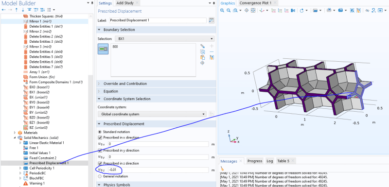
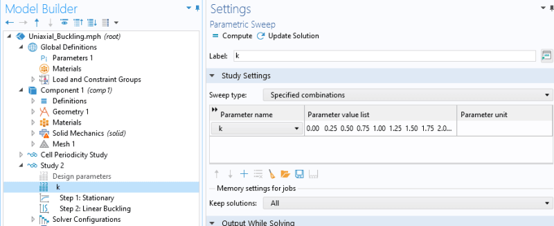
I have a working model, where a linear buckling analysis is done in "Study 2" for the unit cell as seen to the right.

1_excqim.png


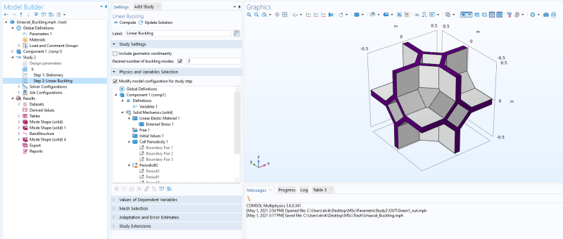
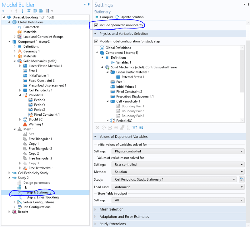
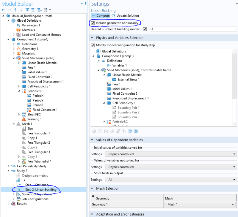
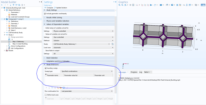
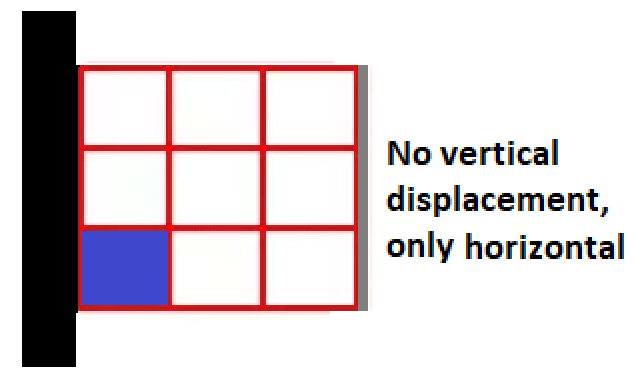
I need to do a uniaxial displacement along the x-direction, and perform linear buckling analysis. A blue rectangle represent the unit cell seen above. So the "beam" will consist of 3x3 unit cells. It is fixed on the left and vertical displacement is restricted on both right and left side. Does anyone know how I could go about extending my model (Pic 1) to the illustration below (Pic 2)?

2_f7twbt.png


Ps. I have checked out application gallery, and there are linear buckling analysis applications, and uniaxial compression applications, but could not find both in one.
 
Replies continue below

Recommended for you

Copy this cell (using pattern) and make sure that Form Union option is selected so that you don't have to define contact between parts. Then apply proper boundary conditions to faces on the left and on the right.

Also, you can use prescribed displacement as load in linear buckling analysis.
 
I think it worked, the results I got look reasonable. I made it 1x3 just to experiment. Do the boundary conditions look reasonable to you?

1_mjo1at.png


2_o7gjbl.png


And based on all this, could I ask how to go about performing a nonlinear buckling analysis? - since the one I just did is a linear buckling analysis.
 
For your assumptions stated in the first post, boundary conditions look correct.

Nonlinear buckling analysis is performed as regular static simulation but with geometric nonlinearity enabled, Comsol doesn’t have any special procedures for that. But you may have to use the continuation solver and this requires some additional settings. Another issue is the definition of imperfections. However, there are some articles about that and examples on Comsol’s website.
 
Could you give me some pointers on how to get started with the continuation solver? - I did tick "Include geometric nonlinearity" at Step 1 and Step 2 in my study, but cant find the continuation solver and its settings.

1_ikf3jw.png

2_a6lb5o.png
 
This continuation solver is basically Auxiliary sweep in Study Extensions tab of the Stationary solver menu. The whole procedure is described in the article "Buckling, When Structures Suddenly Collapse" available on Comsol’s website and there are also some examples in Application Gallery.
 
Thank you FEAway, before I wrap up this thread could I just ask:

Do you think its necessary to add anything in the blue circled area?
1_umlv8a.png


I have this sweep (k-values) already set, not sure if theyre related.
2_apgmtj.png


And when I run the study this way, is it correct to say we are investigating the influence of geometrical nonlinearity under finite deformation?
 
Yes, that’s where you add the continuation parameter.

I think that you can call it this way.
 
Status
Not open for further replies.

Part and Inventory Search

Sponsor