Continue to Site

Eng-Tips is the largest engineering community on the Internet

Intelligent Work Forums for Engineering Professionals

  • Congratulations waross on being selected by the Eng-Tips community for having the most helpful posts in the forums last week. Way to Go!

How to fix a planetary gear 2

elinah34

Mechanical
Aug 19, 2014
135
Hello,

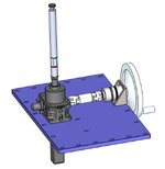
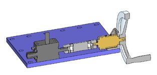
I am wondering how is connecting a planetary gear to the attached sub-assy is recommended?
I used 2 brackets, but I am not sure it's ok.

Capture2-2.JPGCapture.JPG
 
Replies continue below

Recommended for you

I don't know that I've ever seen one fixed rigidly on both ends. That thermal expansion needs to go somewhere. They are always fixed on the low speed end.
 
I don't know that I've ever seen one fixed rigidly on both ends. That thermal expansion needs to go somewhere. They are always fixed on the low speed end.
And fixing it on one side and letting it be hang is robust enough? I am not experienced in this field (gears etc.) so I am really asking.
 
I don't know that I've ever seen one fixed rigidly on both ends. That thermal expansion needs to go somewhere. They are always fixed on the low speed end.
and can you tell me please why on the low speed side?
 
My concern is alignment. There is no way your two mounting points will be in perfect alignment. You are placing your gearbox in a bind.
Talk to the gearbox manufacturer and learn their recommended mounting method.
 
That gearbox looks to have the same diameter input and output shafts - is it a low-ratio unit? The thermal expansion comment seems like good advice, however, since this appears to be hand cranked you may not have much heat generation.

You could probably get a lot of comments on alternate arrangements with a little more info on duty-cycle and required output torque and RPM at miter gearbox.
 
Last edited:
The low speed end of the gearbox sees all of the force multiplication. If you mount from the high speed end you're going to transfer all of the generated forces through the gearbox housing.
 
My concern is alignment. There is no way your two mounting points will be in perfect alignment. You are placing your gearbox in a bind.
Talk to the gearbox manufacturer and learn their recommended mounting method.
There is a clearance between the flange's hole and the gearbox cylindrical interface, so there will still be some flexibility and no over constraint. Something else might be a problem - if the brackets won't be enough perpendicular to the purple base plate there will be some internal undesirable strains.
 
That gearbox looks to have the same diameter input and output shafts - is it a low-ratio unit? The thermal expansion comment seems like good advice, however, since this appears to be hand cranked you may not have much heat generation.

You could probably get a lot of comments on alternate arrangements with a little more info on duty-cycle and required output torque and RPM at miter gearbox.
I am adding a picture that should give some additional information.
 

Attachments

  • 20250115_193456.jpg
    20250115_193456.jpg
    1 MB · Views: 15
Didn't connect that you were using this for a speed increaser. Most comments seem unchanged, although maximum forces will be at input end. I have made some hand cranked gizmos over the years and can comment that most operators are not too happy about needing to making more than a couple of revolutions of the wheel. You may want to put a tapped hole in the end of the input shaft and then put a keeper plate and screw in after installing handwheel in order to prevent the handwheel from walking off the end of the shaft.

Here is your sketch for easier viewing -

gbox.jpg
 
I say again:
"Talk to the gearbox manufacturer and learn their recommended mounting method."

I do not understand the hesitance of today's young engineers to pick up the phone and talk to a live person at a manufacturer's office. They have Application Engineers there. Those guys have ONE JOB - to help you successfully use their product. Ask them for help and guidance!

Engineering forums are helpful, but they are NOT a substitute for the innate, detailed knowledge of a specific product that one gets from a manufacturer's Application Engineer.
 
Or if you really don't want to deal with verbal communication (and sometimes incorrect info at that), reach out to the gearbox vendor. Or the manufacturer. They will have a document describing the best way to use their device.
 
Didn't connect that you were using this for a speed increaser. Most comments seem unchanged, although maximum forces will be at input end. I have made some hand cranked gizmos over the years and can comment that most operators are not too happy about needing to making more than a couple of revolutions of the wheel. You may want to put a tapped hole in the end of the input shaft and then put a keeper plate and screw in after installing handwheel in order to prevent the handwheel from walking off the end of the shaft.

Here is your sketch for easier viewing -

View attachment 3551
Hey and thanks for replying.
What do you mean by "keeper plate"?
I thought about locking the handwheel axially by a wide washer and a screw that will connect the input shaft end.
 
I say again:
"Talk to the gearbox manufacturer and learn their recommended mounting method."

I do not understand the hesitance of today's young engineers to pick up the phone and talk to a live person at a manufacturer's office. They have Application Engineers there. Those guys have ONE JOB - to help you successfully use their product. Ask them for help and guidance!

Engineering forums are helpful, but they are NOT a substitute for the innate, detailed knowledge of a specific product that one gets from a manufacturer's Application Engineer.
Hey, I took your advice and talked to the application engineer.
He said that fixing the gearbox from one end is good enough.
I am adding some updated pictures
1.JPG
2.JPG
 
What do you mean by "keeper plate"?
I thought about locking the handwheel axially by a wide washer and a screw that will connect the input shaft end.

Yes, something like your washer that will "keep" the wheel on the shaft besides the setscrews on the key. Ideally, the hub of the handwheel bears on a shoulder and the "keeper" keeps the handwheel drawn firmly against that shoulder. For a shaft with no shoulder the "keeper" might be fastened to both the handwheel hub and the end of shaft with multiple screws so that the handwheel will not be able to move axially along the shaft in either direction. This also will prevent the key from sliding out of the keyway, if it is an open ended keyway.
 
Why is it important to prevent any axial movement of the handwheel relative to the shaft? I initially thought to leave a small clearance of about 0.5 mm between the "washer" and the wheel planar end face.
In my case, if I tighten the handwheel with the washer, it will be tightened against the gear planar end face, there will be undesirable friction that will be added to the required operating torque.
 
It is only important to add the washer if the handwheel comes lose due to cranking effort of the operator - try it without the washer and if the handwheel comes lose then you may decide to find a solution. There are many ways to create a stepped washer that will not allow the handwheel hub to rub on the reducer.
 
OP
Does the bracket have a bearing.
Doesn't look like it to me.

You are concerned about the operator overloading the radial capacity on the gearbox input? Dunno what that capacity is, or who's using it, and how often. I'd be concerned about it as well.
 

Part and Inventory Search

Sponsor