Continue to Site

Eng-Tips is the largest engineering community on the Internet

Intelligent Work Forums for Engineering Professionals

  • Congratulations cowski on being selected by the Eng-Tips community for having the most helpful posts in the forums last week. Way to Go!

How to Measure Power Tool Shaft Torque 7

Status
Not open for further replies.

HydraulicsGuy

Mechanical
Feb 4, 2020
79
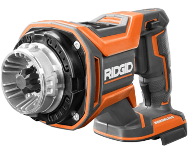
I have a Ridgid MEGAMax Power Base:
Ridgid_yjsyrn.png


I have found a way to make this base power-on without having one of their 3 attachment heads attached (a project in itself!). I will be using it to drive a hydraulic pump. Pump size to be chosen based on Power Base performance. Therefore, I need to know:

(1) no-load RPM
&
(2a) stall torque or
(2b) torque at some other RPM

From those, I can calculate the RPM at any torque, or the torque at any RPM.

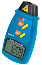
RPM measurement should be pretty straightforward I think. This was recommended:
RPM_Tester_sdqlot.png


My question: What is a simple cheap way to directly measure the torque? I don't want to design a test setup if I don't have to. I did some brief googling but nothing stood out, other than a reply from someone on this forum on another thread, suggesting to measure a base reaction rather than a torque at the shaft. There are no shaft RPM and torque values stated for this Power Base that I could find. There are some values, but they are for the attachment heads, and who knows what kind of gearing takes place inside those. RPM + torque values (together) are extremely difficult to come by on the internet, for any power tool. I have not tried contacting the company. Since it's not the tool's intended use, I'm 100% sure it will be met with disdain. I'm also 100% sure I'll have to correspond with a salesman, and there is only a 25% chance he'll comprehend what I'm looking for. I want to discuss with engineers.

More googling after posting this. Is the answer a "torque transducer"?
 
Replies continue below

Recommended for you

Rigid doesn't publish torque values? I have tools from other producers and they do publish them.

= = = = = = = = = = = = = = = = = = = =
P.E. Metallurgy
 
Do those others publish "rated torque" at an RPM? Just "rated torque"? Stall torque? Do they also publish the no-load RPM? I found all this info bundled together to be very scarce when I was researching.

Ridgid does not publish these values for just the Power Base by itself, at least not that I could find. If you can find them (not the geared final output values, and not the impact energy values that look like torque values), then I will be very impressed and thankful!
 
"Torque transducer" or "torque cell" is correct search term but they are expensive. In addition to the transducer you will need electronics for it.

For stall torque you could connect a lever arm to the shaft and see what weight on the end it will almost lift.
 
I'm hesitant to do the lever arm thing because it would impose a force, in addition to the torque, on the shaft. I'm unsure how the shaft would handle that. I guess the longer the lever, the lower I can make the weight, but still.
 
With these motors the max torque is nearly constant across the speed range, but Makita publishes max torque and no load speed. At least it is something that I can compare.
The simple test is to mount the tool, connect and arm, and then push down on a scale. If everything stays firmly in place you will get a good number. I would be expecting something at least 100ft-lb out of this.

= = = = = = = = = = = = = = = = = = = =
P.E. Metallurgy
 
if you had a weight on a cable, wrapped around a drum … turn the motor on and measure torque, rpm, and work done.

if you want to avoid a shear load on the motor, then have two cables on the drum, providing a couple on the motor (yes, one side would need to go around a turning block).

another day in paradise, or is paradise one day closer ?
 
How about this: lever arm with equal stickout on both sides, with each end of the lever arm pushing against a scale? Or one end push against a scale, the other against "ground". That would take applied force out of the picture, and leave only torque. I would only need to design a lever to mate with the shaft. Doesn't sound too bad.

Brian or others: Approximately how much would a torque transducer or torque cell, with electronics, cost?
 
It says "powering the angle drill". There is probably some gearing inside the angle drill head. I'm guessing it's not representative of the torque of the Power Base itself. The next question asks about torque, and they say "The torque would depend on what attachment is used on the power base".
 
Use a dial recording torque wrench to measure stall torque.

Ted
 
It's an 18V battery driven tool. Do a search on HD for comparable systems:
--> 1200 in-lb
"XWT12ZB - BL Brushless Motor delivers 130 ft.lbs. of Max Torque and 230 ft.lbs. of Nut-Busting Torque"

TTFN (ta ta for now)
I can do absolutely anything. I'm an expert! faq731-376 forum1529 Entire Forum list
 
Lots of ways to rig up a test. Like putting a flat-blade paddle stirrer into water and putting the device on a vertical hinged block with a pull-scale (like for weighing fish) at a known radius to the hinge. Make it perpendicular and you can easily get within 10%. You can adjust the insertion into the water or the water level to set torque/RPM for whatever trigger position.

It may also be possible to monitor the current/voltage and, since power is rotation rate times torque (get the correct units) and you can measure the rotation rate, then you divide out from the power input in watts to get delivered torque (neglecting friction and other losses; again 10% should be easy.)
 
I will need to know for this tool. I hear you that it should be close to other tools, and it probably will be. But I really need to know pretty accurate values for this particular tool.

(Makita's specs are all over the place. Another bulleted item says "XFD11ZB - BL brushless motor delivers 350 in. / lbs. of max torque". Much much different from 130 and 230 ft-lbs. And what is "max torque"? Stall torque? Or some other nebulous 'rated torque' value at some RPM? This is a good example of the data I encountered when researching this. Hard to determine what output they actually have when they use nebulous terms.)

Brian, thanks. Whew, 10k is going to be way too much!

Ted, can you explain what the test setup would be for the dial recording torque wrench? Mate the wrench to the shaft via a designed connection, hold down on the wrench while turning on the tool, apply force to the wrench until shaft stops spinning, record stall torque? This method applies a load to the shaft in addition to the torque, which I'm trying to avoid. Do they make one with a handle that allows a couple to be applied?
 
Ebay has some cheap torque transducers. Search for "torque transducers". Looks to be a lot of GSE torque wrench transducers.
 
1) Using the factory drill head chuck a shaft projecting from a pillow block bearing in it. (Say, bench to pillow block for power head support.

2) Using a string or rope have the shaft raise a pail with weight in it like a windless.

3) Start light and observe the speed and listen for the motor labor.

4) Work up the weight until you feel the motor dropping off it's power curve.

5) Put up a measuring stick possibly high contrast black and white paper.

6) Measure the speed the bucket rises with the load you consider the "maximum reasonable load" using a video camera watching the bucket and the measuring stick. Just like your college kinematics labs.

7) Remove the drill-head and manually turn the input to calculate the gear ratio.

8) Walk the math back from the gear ratio to get the actual power unit torque and speed at the "maximum reasonable load". This will be more accurate than any direct shaft schemes and will reduce the observational speed requirements down to something human approachable.

A) This method removes all force from the output shaft because the head mount does this just like your pump adapter will.

B) You will be able to judge the actual ability at speed instead of useless stalled or boundary conditions.

C) Definitely back off from "maximum reasonable load" for your design figures depending on operational considerations. E.G. If your use is short low duty cycle then don't back off much. If it's high duty cycle back things way off.

D) Do include cooling time during testing or your results may not be accurate.


Keith Cress
kcress -
 
Status
Not open for further replies.

Part and Inventory Search

Sponsor