Continue to Site

Eng-Tips is the largest engineering community on the Internet

Intelligent Work Forums for Engineering Professionals

  • Congratulations SSS148 on being selected by the Eng-Tips community for having the most helpful posts in the forums last week. Way to Go!

How to Measure Power Tool Shaft Torque 7

Status
Not open for further replies.

HydraulicsGuy

Mechanical
Feb 4, 2020
79
I have a Ridgid MEGAMax Power Base:
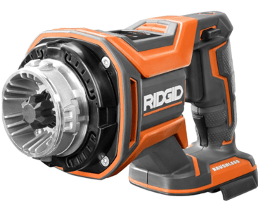
Ridgid_yjsyrn.png


I have found a way to make this base power-on without having one of their 3 attachment heads attached (a project in itself!). I will be using it to drive a hydraulic pump. Pump size to be chosen based on Power Base performance. Therefore, I need to know:

(1) no-load RPM
&
(2a) stall torque or
(2b) torque at some other RPM

From those, I can calculate the RPM at any torque, or the torque at any RPM.

RPM measurement should be pretty straightforward I think. This was recommended:
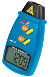
RPM_Tester_sdqlot.png


My question: What is a simple cheap way to directly measure the torque? I don't want to design a test setup if I don't have to. I did some brief googling but nothing stood out, other than a reply from someone on this forum on another thread, suggesting to measure a base reaction rather than a torque at the shaft. There are no shaft RPM and torque values stated for this Power Base that I could find. There are some values, but they are for the attachment heads, and who knows what kind of gearing takes place inside those. RPM + torque values (together) are extremely difficult to come by on the internet, for any power tool. I have not tried contacting the company. Since it's not the tool's intended use, I'm 100% sure it will be met with disdain. I'm also 100% sure I'll have to correspond with a salesman, and there is only a 25% chance he'll comprehend what I'm looking for. I want to discuss with engineers.

More googling after posting this. Is the answer a "torque transducer"?
 
Replies continue below

Recommended for you

My hunch is that if you have hacked the unit so that it will deliver max power then you will likely get constant torques up to some speed and have it drop off linear from there. I also fairly sure that there will be a max speed that is well below the zero torque level.
I can tell you that my battery tools only see slight speed drops when subjected to 'normal' loads.

= = = = = = = = = = = = = = = = = = = =
P.E. Metallurgy
 
You really should monitor the current being drawn during your test. You will probably see it rise on some curve then possibly change radically during overload. This can help you arrive at the aforementioned "max reasonable load".

Keith Cress
kcress -
 
Well he said he had"found a way" to get it to run.

These things sometimes use an electronic signal or chip as well as a mechanical pin.

I would just use one of the attachment heads myself.

Remember - More details = better answers
Also: If you get a response it's polite to respond to it.
 
LittleInch, I was able to disassemble one of the attachment heads to a point where I could then take 2 of its components (a flange piece and a 5-lead plug), connect them to the Power Base, and get the Power Base to run. Just pulling the trigger on the Power Base out of the box, even with charged battery, resulted in no shaft motion. My thinking to try what I did was decently clever, but the fact that it worked was just sheer luck. In my picture above, you can see the silver flange piece from the head, attached to the Power Base.

I will review you guys' other recent posts about the Power Base's motor behavior a little later to wrap my mind around it.
 
So a little bit of a sag in the theoretical straight line, but not terribly far off. If this holds true for the Power Base motor, then by testing at the 2 end points, and a couple points in between, I should be able to develop a pretty accurate curve.
 
Just Do It!

Prony brake

From <
Prony brake
mechanics

From <
Prony Brake for Testing Small Motors

From <
The Design, Construction, and Use of a SMALL PRONY BRAKE

From <
Bench Top Dynomometer
From scrap wood, spring force scale and tachometer
From <
Diy Engine Dyno
Photos at bottom of posting
From <
Pick a scheme and go with it, but don't rely on guesses and visual shaft speed (without a strobe tachometer)!

Walt
 
We will be. But we're going the hydraulic pump route, and calculating RPM and torque rather than measuring them directly. Boss's orders.
 
**UPDATE**

Trouble in paradise: the Ridgid Power Base shaft spins at nearly 16,000 RPM at full trigger pull, as measured by a contact tachometer. At initial partial trigger pull, it is approximately 2800 RPM. Utilizing this partial trigger pull to stay within pump RPM limits, we have found that the torque is not enough to even turn the pump more than a couple revolutions before the Power Base trips and goes into fault mode. It is a 4.9 cc pump. We were attempting to send pump flow over a relief valve backed out all the way to its lowest setting of 100 psi. Assuming the pump is 50% mechanically efficient at this very low pressure, the calculated torque required to send flow over the relief valve (assuming no other pressure drops) would be ~10 lb-in. So the Ridgid Power Base apparently has a stall torque around 10 lb-in, give or take.

We will either have to utilize the attachment head with its ~11:1 gearing, or extract and utilize said gearing, or abandon this Ridgid Power Base idea altogether and look into another power tool motor base with lower speed / higher torque.
 
That is the whole point of reduction gearing, trading rpms for more torque. Running your tool at partial rpms is just wasting the full capability of the tool.

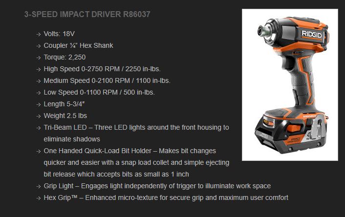
Alternately, is selling at HD for free with the purchase of the two batteries for $99, AND it claims 2000 in-lb torque.


TTFN (ta ta for now)
I can do absolutely anything. I'm an expert! faq731-376 forum1529 Entire Forum list
 
Even at full RPMs, I believe the torque wouldn't change, and therefore still wouldn't be enough. So we're not wasting torque. But had it been able to turn the pump, we would be wasting power at the partial RPMs (wasting full capability as you said). We were just trying to get it to work within the pump's RPM limits. Pumps can't handle 16,000 RPMs. Just trying to get some fluid flowing and data collected, as a starting point.

Yeah we may have to explore something like that Ryobi or other similar ones. The handle shape isn't ideal for picking up the entire power unit like we want to do. Would prefer a D-handle shape for that. But we may have to compromise on that.
 
I don't know if it has been mentioned in previous post, so here is my take about this post. From the picture the Ridgid MEGAMax power supply is from a battery, however if it can be operated directly from an electrical outlet, measure the input current and the RPM under various loads at the attachment head. Knowing the current input and voltage, you can calculate the output horsepower values of course you'll need to estimate efficiencies of the electric motor and its power train. Once you have estimated the horsepower, knowing the attachment head RPM values, you can calculate the torque values under the various loads. Equations to the horsepower and torque can be referenced in any engineering handbook or perhaps Wikipedia.
 
So either use one of the existing gear heads that fit this base to get you into the correct speed range or find another tool.
Look at Hilti and DeWalt (20V).

= = = = = = = = = = = = = = = = = = = =
P.E. Metallurgy
 
Even at full RPMs, I believe the torque wouldn't change, and therefore still wouldn't be enough.

You missed my point. A speed reduction gear converts high rpms/low torque to lower rpms/higher torque. This is the mechanical advantage generated by the gearing; it's like using a compound pulley to lift heavy objects.

TTFN (ta ta for now)
I can do absolutely anything. I'm an expert! faq731-376 forum1529 Entire Forum list
 
I understand the concept of trading RPMs for torque. I'm not sure what point you were trying to make, honestly. Ordinarily, a pump doesn't care. Just choose one with the right displacement to get the psi and GPM needed, regardless of whether the motor RPM is sky high or ultra low. In this case I can't because the RPM exceeds the RPM limit of the pump. If the RPM had been 7000 (still a really high number) instead of 16000, I could make a pump work. The RPM would still be really high, and the torque really low, but I could just choose a very small displacement pump.
 
So either use one of the existing gear heads that fit this base to get you into the correct speed range or find another tool. Look at Hilti and DeWalt

That's what I said in my update post. I was just updating if people were interested in hearing the results. I researched other brands when I was doing my initial research, and from what I can recall (it was like 8 months ago), I found only 2 good candidates with a D-handle. I chose the Ridgid because it looked like the most easily adaptable to a pump. I didn't expect 16000 RPM.
 
Clearly at that rpm you need less than 1cc/rev pump.

Ted
 
What about this?

shows the impact of variable speed, but if you want around 2500 rpm seems ideal?

drill_ode7sm.jpg
speed, but if you want around 2500 rpm seems ideal?


Remember - More details = better answers
Also: If you get a response it's polite to respond to it.
 
Status
Not open for further replies.

Part and Inventory Search

Sponsor