Continue to Site

Eng-Tips is the largest engineering community on the Internet

Intelligent Work Forums for Engineering Professionals

  • Congratulations KootK on being selected by the Eng-Tips community for having the most helpful posts in the forums last week. Way to Go!

How to measure true postion

Status
Not open for further replies.

aehernan88

Mechanical
Jul 26, 2019
6
Hi, I am having a hard time understanding the true position for the Ø.199 holes in this drawing and how to measure them during inspection.

When the hole diameter is the smallest allowed or at MMC(.198) the center position of the hole can vary by Ø.002 from the true position. Is that correct?

What does the lower True Postion / .000 MMC block mean?

What's the best way to measure this using a Vision System?

What about using a functional gauge? Would the pins be Ø.197? What would be the position of the pins?
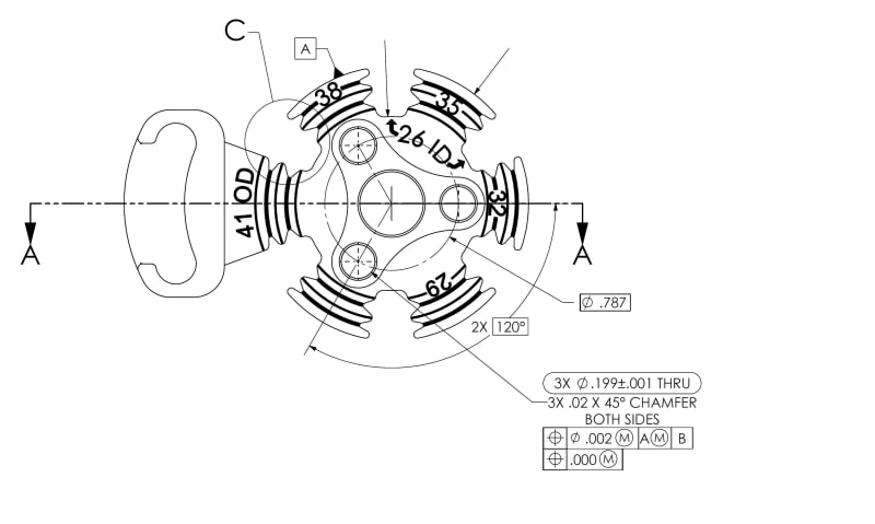
True_Position_ou43wi.jpg


Thank you for the help!
 
Replies continue below

Recommended for you

aehernan88,
[ol 1]
[li]What is the drawing interpretation standard?[/li]
[li]What portion(s) of that standard have you read?[/li]
[li]What is datum feature A? It looks like a small portion (roughly 40°) of a cylindrical surface, but that doesn't make much sense.[/li]
[li]What tolerance(s) apply to datum feature A?[/li]
[li]What is datum feature B?[/li]
[li]What kind of vision system do you have in mind?[/li]
[/ol]


pylfrm
 
1. ASME Y14.5M-1994
2. I have read section 2
3. Datum A is the outside face of that cylindrical surface
4. Datum A is Ø1.614 ±.005. Same dimension applies to the other 4 portions of the circle.
5. Datum B is the flat surface on the opposite side of this view.
6. STARLITE GX OPTICAL MEASUREMENT SYSTEM

Thank you!
 
aehernan88,

You are calling up datum feature[ ]A at MMC. Your drawing is not clear that this is the full diameter. What do people think of calling up a partial radius at MMC?

Let us assume you have sorted out your datums, and you can pick these up on your machine. Your part is very accurate. You can inspect to the four quadrants of each your holes. This will allow you to calculate the position of each hole and the diameter. You can compare the diameter values with the ones you measured with micrometers or measuring pins, as a sanity check. You can design a fixture to simulate datum[ ]A at MMC. If your part is small, you can wiggle it around to position the holes.


--
JHG
 
As to what the lower True Position / .000 MMC block means, it means that at MMC the 3 holes have to be positioned perfectly relative to one another.

"Know the rules well, so you can break them effectively."
-Dalai Lama XIV
 
@drawoh True position requires a feature of size, which roughly means, a feature with two opposing points.

I'm not a vegetarian because I dislike meat... I'm a vegetarian because I HATE PLANTS!!
 
aehernan88 said:
I am having a hard time understanding the true position for the Ø.199 holes in this drawing and how to measure them during inspection.

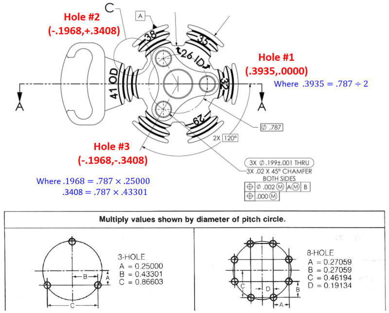
Before your inspection, you need to find out the basic dimensions of each hole, so you will convert the coordinate system from polar to traditional as shown on the figure below.
2019-07-31_114054_hsmfvx.jpg


aehernan88 said:
When the hole diameter is the smallest allowed or at MMC(.198) the center position of the hole can vary by Ø.002 from the true position. Is that correct?
The upper segment position tol allowed is Ø.002 at MMC while the position tol allowed on the lower segment is Ø.000 at MMC.

aehernan88 said:
What does the lower True Postion / .000 MMC block mean?
As ewh mentioned, the lower segment controls the spacing within the hole pattern.

aehernan88 said:
What's the best way to measure this using a Vision System?
We are using CMM on our inspection, sorry for I can’t give any comments here.

aehernan88 said:
What about using a functional gauge? Would the pins be Ø.197? What would be the position of the pins?
Absolutely, functional gage will be a better way on your case, since there is a MMB modifier on the primary datum feature, it will save your hard time to calculate the datum shift allowed and analyze on the hole pattern acceptance. But you need two gages on this case because of each segment of a multiple single-segment position control must be verified separately.
The gage pin size and its position of the upper segment is 3X Ø.1960 +.0002-.0000, |POS|Ø.0002|A|B|, and for the lower segment is 3X Ø.1980 +.0002-.0000, |POS|Ø.0000|.

By the way, 2X120° need to be changed to 3X120°, and the diameter symbol missed on the lower segment FCF. Hope my 2 cents will help you.

Season
 
Status
Not open for further replies.

Part and Inventory Search

Sponsor