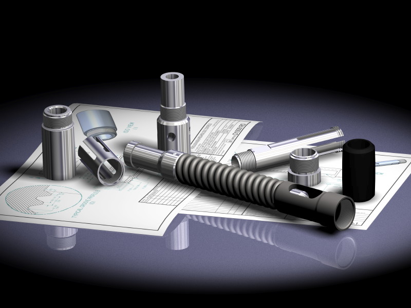
First get an image file of a drawing, be it of a CAD generated drawing or a scanned in paper drawing. The create a Sheet Body of the desired size and shape, and then apply a 'texture' to the face of the Sheet Body using the image file of the drawing using one of the texture options that says place a single image fitted to the face.
For some other, although older, images created using NX (Unigraphics back then), go to...
...and scroll to near the bottom of the page, although some of the earlier images does show how things have evolved over the years (that first image the Starship Enterprise was done in 1977).
Of special interest is that image of the cutaway of the butterfly valve with the magnifying glass...

...as the 'magnified' part of the image was NOT faked. I actually created a 'magnifying glass', positioned as you would expect it to be, with an accurately modeled 'lens' assigned the material Glass which included not only the color (clear) but also an index of refraction. In fact, if I were to have moved the magnifying glass back further away from the butterfly valve, the image would have eventually reversed itself as would happen in the real world. The rendering engine we use with NX was developed by a group of optical physicists originally intended for designing optics, but they discovered that they could sell many more licenses if they added materials and rendering capabilities, however they left in all of the code which simulated the way light passed through materials, such as glass, which has an index of refraction. In fact, I once messed around with trying to position a series of lens to simulate a telescope but never really finished it, however it was showing promise ;-)
John R. Baker, P.E.
Product 'Evangelist'
Product Design Solutions
Siemens PLM Software Inc.
Industry Sector
Cypress, CA
To an Engineer, the glass is twice as big as it needs to be.


