Continue to Site

Eng-Tips is the largest engineering community on the Internet

Intelligent Work Forums for Engineering Professionals

  • Congratulations KootK on being selected by the Eng-Tips community for having the most helpful posts in the forums last week. Way to Go!

How to Output Results for Each Increment From Group in FEMAP 1

Status
Not open for further replies.

jonny1230

Materials
Feb 7, 2015
14
Hi Everyone,

I have just started using FEMAP after many years of using Abaqus (which is way more friendlier). Just like in Abaqus one can create a set and request a specific output for that set once analysis is finished, Can we do that in FEMAP too ? I am modelling a basic composite shell, applied tensile deformation and made a group to get output from, but the post-processing options are so complex that I just cannot figure out how to get the output of for example load for every increment.

Can someone please help ? I will be grateful.

Many Thanks in Advance
 
Replies continue below

Recommended for you

I haven't done time dependent loads (how I read "load for every increment")

You can obviously have different "increments" as different loadcases.

You can output loads for specific groups.

If this is heading in the direction you want to go, I can add details.

I found FeMap very user friendly, but then I came from PATRAN.

another day in paradise, or is paradise one day closer ?
 
Dear Jonny,
GROUPS in FEMAP is very powerful, I use it a lot, specially for postprocessing.
You have a menu to create groups.
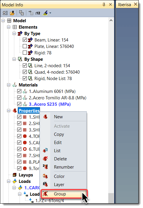
Also in the MODEL INFO tree you can click with the right mouse button (RMB) in say PROPERTIES then select GROUP and FEMAP will create different groups with elements for every property:

groups-by-properties_anhh3a.png


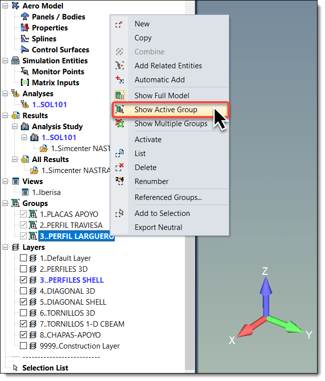
All your groups will appear in the MODEL INFO tree under GROUPS: to postprocess results in the elements of the group simply RMB in the group and select SHOW ACTIVE GROUP: from now in advance when you plot any output vector like vonMises stress in elements only the results for the elements of the active group will appear in the screen. And is more: the legend of results will be limited to the values of the active group, not the full model.

groups-show-active_ezymmv.png


To return to the full model click in GROUPS and select SHOW FULL MODEL

Enjoy!.
Best regards,
Blas.

~~~~~~~~~~~~~~~~~~~~~~
Blas Molero Hidalgo
Ingeniero Industrial
Director

IBERISA
48004 BILBAO (SPAIN)
WEB: Blog de FEMAP & NX Nastran:
 
Hi Both, Many thanks

@Blas Molero

I am looking to plot a load versus displacement curve from the group set I have created, and trying to get output from that (apparently struggling with it). The group comprises of node set of a region on the part subjected to tensile load. Should I just see the what load values are at the end of the load step, by isolating the group and in post processing and get the load points for every node from this set and find the average value.

I have turned the non linear mode on, and wanted to capture any non-linearity in the load curve but I guess I cant do that since, the software takes 1 increment to solve, might need to make the load time dependent.

If you can help or advice.

Mayank
 
Hello!,
The load is the applied load, is in the title of the output set, you can compute the applied load as well multiplying the time of the analysis step by the applied load in the model. Also what I do in general is to define an spider RBE2 rigid element with the potential constrained nodes and fully constraint the independent node, there you can compute the reaction force that is equal to the applied load.

For displacements you can pick any node and list results using the DATA TABLE. What I do is to export results to excel and compose the X-Y CURVE there.

Best regards,
Blas.

~~~~~~~~~~~~~~~~~~~~~~
Blas Molero Hidalgo
Ingeniero Industrial
Director

IBERISA
48004 BILBAO (SPAIN)
WEB: Blog de FEMAP & NX Nastran:
 
@Blasmolero

Many thanks, I am now getting my hands on it quite well than what I did before posting this thread. I just have 2 questions:

1. When I apply a load of 50 N, the output load only goes upto 2 N, maybe the model is finding is hard to converge.
2. In order to apply incremental loads, like 5N, followed by 10N, etc. do I need to specify multiple load steps ?

I thank you in advance for this. Its just that Abaqus, did the result output much easily, but I understand this is a much more advanced version of abaqus.

Many thanks again
 
Hello!,
I run Simcenter NASTRAN FEA solver with FEMAP, not abaqus, if you define a nonlinear analysis with an applied load of 50N and the last converged result is for 2N only, then you have a problem: either your analysis failed because a buckling bifurcation point was reached, or the total time is not defined for 100% loading. Investigate the output files and search for a fatal error to see if you have instability problems: use displacement control or arc-length methods instead force control.

Also, increasing the number of time steps is the way to help convergence, use 50 times steps and see if the solution converge.
Best regards,
Blas.

~~~~~~~~~~~~~~~~~~~~~~
Blas Molero Hidalgo
Ingeniero Industrial
Director

IBERISA
48004 BILBAO (SPAIN)
WEB: Blog de FEMAP & NX Nastran:
 
Hi

Many thanks. I have been able to get the outputs comfortably now.

I meant by my last line that abaqus was easier to use in terms of exporting the results but NASTRAN with FEMAP is much more advanced.

I am trying to model the composite laminate, I can get the stiffness's fine but when I enter the stress limit values, and failure type, and run the model, the error message comes up. Do know how I could fix it ?

Sorry for asking too many questions here
 
What version of Femap are you using?

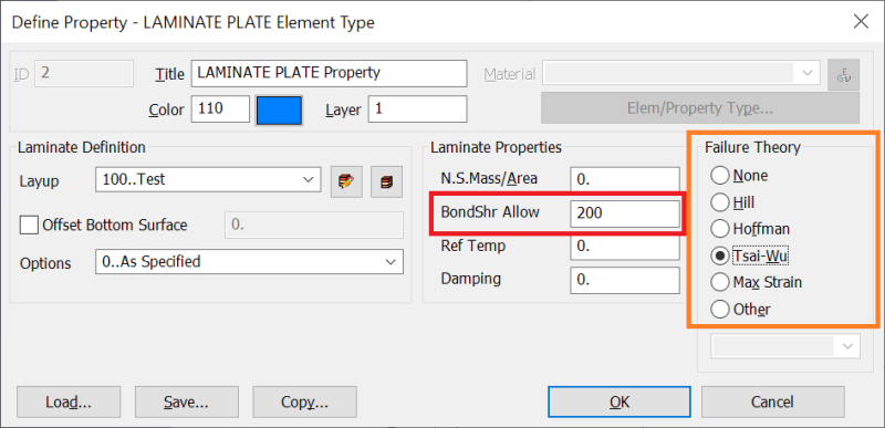
In your laminate property, do you have the "Failure Theory" set and also the "BondShr Allow" set?

Are you getting an error right when you analyze or preview the deck? What does the error say?

 
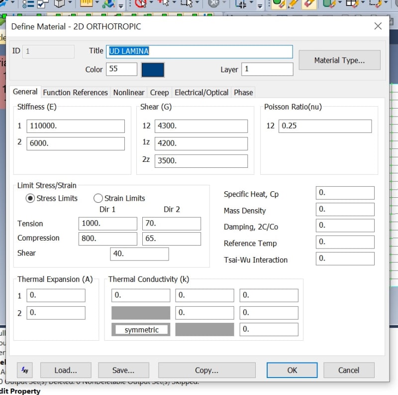
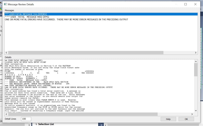
Hi, I am using FEMAP 2020 version. I set the laminate property in the element stage, but the analysis produces errors such as
image1_yujtru.jpg

image2_sreswi.jpg

image_3_rkw1an.jpg


I even checked the material orientations but it still shows me the same errors. I dont have the bondshr values,

Could you advice ?

thanks in advance
 
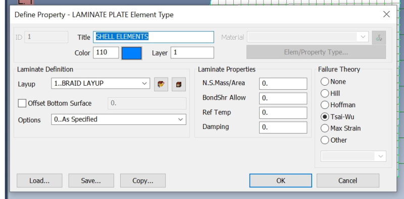
You must enter a "BondShr Allow" in the laminate property dialog if there is a Failure Theory specified. In the Nastran quick reference guide (QRG) it states for PCOMP: "SB - Allowable shear stress of the bonding material (allowable interlaminar shear stress). Required if FT is specified. (Real > 0.0)"

BondShrAllow_lgczns.png
 
Status
Not open for further replies.

Part and Inventory Search

Sponsor