Continue to Site

Eng-Tips is the largest engineering community on the Internet

Intelligent Work Forums for Engineering Professionals

  • Congratulations cowski on being selected by the Eng-Tips community for having the most helpful posts in the forums last week. Way to Go!

How to reduce torsion on the beam? 3

Status
Not open for further replies.

Blackstar123

Civil/Environmental
May 5, 2013
253
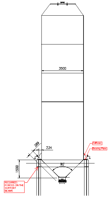
I've a structure supporting a steel silo.
image_chdrws.png


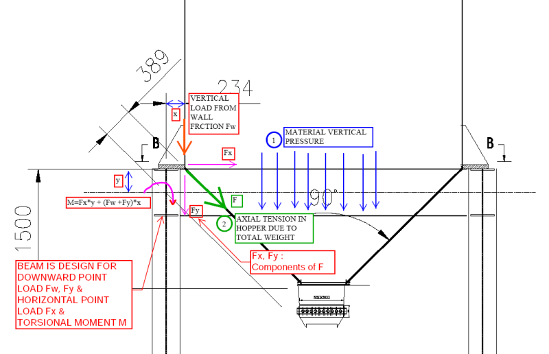
I've calculated forces on the supporting beam assuming the load path as shown in attached Figures.
image_scen5y.png


I'm trying to pass the supporting beams in torsion, which is coming out to be quite large due to heavy load (Tu = 130 KN-m = 1145 kip-in). There's a maximum limit beyond which I cannot increase the beam width further. This left me to play with the depth of beam and thicknesses only. Increasing depth is inadvertently increasing the eccentric moment due to horizontal force.

I'am thinking it's better to look at options to reduce the torsion first than keep on trying different beam sizes.

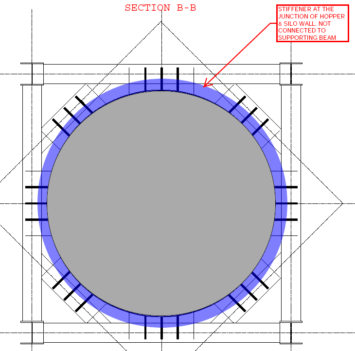
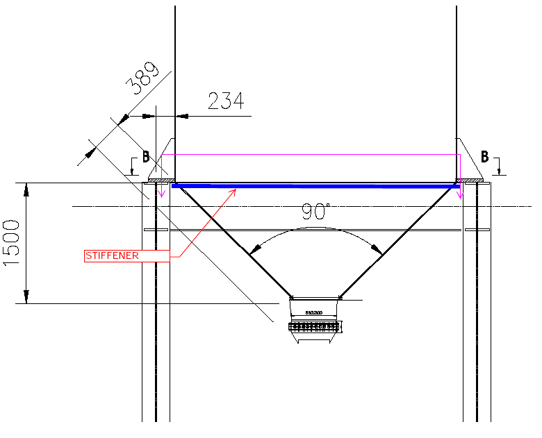
Question is, If a stiffener is provided at the junction of silo wall and hopper as shown in the figure below (which is not connected to supporting beam) then am I right in presuming that the horizontal force will not be transferred to the beam and it will be in equilibrium due to axial force in the stiffener?
image_nopilp.png


image_x98zm8.png


P.S. I am not responsible for the design of steel silo. It is in the scope of others.
 
Replies continue below

Recommended for you

wouldn't the lateral forces at the base, due to the inclined force on the "funnel" walls reacting the vertical weight force, be reacted internally (like in the ring around the base) rather than travelling down the support structure.

make a free body of the load in the silo and the supports for the silo (into the ground). I see the ground supports reacting vertical loads, and lateral loads due to lateral applied loads. These lateral reactions should be carried by inclined "truss" members.

Now if your silo doesn't have a complete ring (or even a ring of connected fittings) around the base, then maybe you've got a problem !

The silo design may not be yours, but you can see how it affects your structure. Maybe look at existing silos ?

Maybe your hands are tied, and you Have to work with the geometry given you? Well then, make your design look silly (ie large, expensive, complicated), reacting these internal loads, when there are better solutions available.

another day in paradise, or is paradise one day closer ?
 

You are wrong..

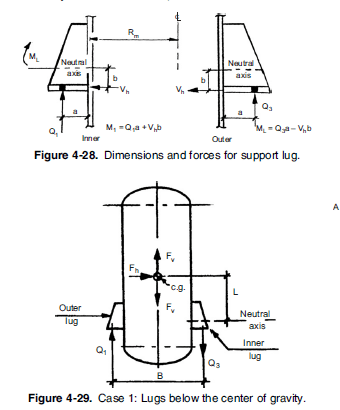
You are not responsiblle for the design of silo and supporting lugs....The snap below is taken from ( PRESSURE VESSEL DESIGN MANUAL 4th ed. Dennis R. Moss ).

supporting_lugs_lpzlfw.png
 
You should use braced frame. It's not rare that silo support beam get very deep/stiff.
 

I pressed with mistake to submit instead of preview.. the lugs may need compression and tension ring stiffeners at the bottom of the silo. But this is the scope of vessel supplier.
 
If the silo is in the scope of others, specify where the line of support is for the bracket (under your beam centerline).

The silo will be designed for this eccentricity. This is normally how it is done. Don’t waste you time worrying about torsion on your beams.
 
Normally, the silo would have a compression ring at the junction. Depending on size and loading, this could be a horizontal ring or girder on the outside, or could consist of thickened areas of plate in the shell and cone. If it can be accomplished with thickened areas, that simplifies some of the other detailing. Anyway, that compression ring would be intended to take all the horizontal component of loading from the cone bottom.
Usually, a silo is much thinner-walled relative to its size than a pressure vessel, and using lug supports may or may not work. In some cases, there will be a second stiffener at the top of those lugs to resist rotation of the lugs.
I would assume primarily a vertical load at the lug-to-chair point, and confirm that the silo is adequately designed to handle rotation of the lug. You will have some horizontal loads due to seismic or wind. If the silo operates hot, you'll have thermal loads.
It may be possible to move the support points closer to the shell or even aligned with the shell to reduce the eccentricity.
 
There is no inclined tension as indicated in your drawing, the weight in the outlet corn just distributed to the support legs as gravity later, the outward horizontal loads cancel each other. The beams will have torsion if the legs are off center, then the column will subject to biaxial bending. You will need compression stiffener under the support legs, and the bracing gusset plate will serve duel functions - support the bracing, and assist in resisting bending.

image_ihiz3e.png
 
I think we're all saying the same thing. In your design the "stiffener at the junction of the hopper and the side wall" (as you not in red text) is a ring internally reacting the lateral loads from the funnel base. Your support is concerned with vertical loads and lateral loads (like wind). Your support should have lots of capacity in the vertical direction and a smaller capacity (two? diagonal braces, in two separate planes; why not one diagonal per vertical?) to take lateral loads.

another day in paradise, or is paradise one day closer ?
 
If you get torsion you can't handle in those girders.....a alternative could be to have some kickers going from the bottom of the girders subjected to that to a lower level of steel (wherever you can fit it in). This basically transforms the torque into a doable axial and/or lateral load that you can then get to the columns.

I've done it a few times when I've been forced to put stuff like a process column on a steel frame. (I.e. you get outrageous torques.)
 
The eccentricity seems small, thus the torque. Also, globally speaking, the torques cancel out, the system is quite stable.
 
The eccentricity seems small, thus the torque.

He says in the OP that he's got 1145 kip-in of it.....and he's hit a limit in girder size. So whatever the cause (or whether it cancels itself out)....this is something I've done in the past that can take care of some pretty hefty torques. (If needed.)

 
WARose,

He made mistake in assuming tension in the inclined cone from the load it contents. See his elevation view with indicated forces, and the accompany comments. If you look at the plan again, you'll understand what I was talking about. Yes, I believe you can make it works.
 
He made mistake in assuming tension in the inclined cone from the load it contents. See his elevation view with indicated forces, and the accompany comments. If you look at the plan again, you'll understand what I was talking about.

I saw it.....and you may be correct. But there might be another source we haven't been advised of yet. For something like that, another possible source could be a overturning force (i.e. uplift on one side in the case where the bin is empty/near empty and a lateral load hits).

Whatever might induce a torsion issue.....I just wanted to suggest a possible solution if it cannot be dumped into a girder.

 
Why not provide your method, so someone can benefit from it down the road, if not for this case.
 
First of all, I want to thank everyone who responded.

I've desined RCC silos with hopper resting on a ring beam in the past. The ring beam was designed for similar forces as shown in my original sketch.

This is the first time I'm designing the supporting structure for a steel silo. But I've a pretty clear understanding what the forces at the junction of the hopper and wall will look like.

My understanding is that the tension force in the hopper will be exerting a pull force at the junction. That is it will be trying to straighten out the inclination of hopper at the joint. That inclined force will have a vertical and horizontal component. Since steel is susceptible to buckling due to compression, the horizontal thrust need to be resisted at the junction.

Since the position of the silo support shown in supplier drawings is exactly at the joint of wall with hopper, I believe that this horizontal force will have to be resisted at support unless some other mechanism is provided by silo's designer to resist this pull force as some of the responders implies that there will be a internal ring beam type mechanism provided in the silo.

rb1957 said:
wouldn't the lateral forces at the base, due to the inclined force on the "funnel" walls reacting the vertical weight force, be reacted internally (like in the ring around the base) rather than travelling down the support structure.
...
Now if your silo doesn't have a complete ring (or even a ring of connected fittings) around the base, then maybe you've got a problem !
Yes this is what i was suggesting. If there's a stiff ring around the junction which is not connected to support beam, the horizontal thrust will convert to axial force in the ring. Just like the lateral pressure in the wall is converted to hoop force or axial tension.

Since silo design is not shared with us, I can't comment on this with surity. But I've sent an email to client, requesting them to share the design of steel silo with us.

hturkak said:
You are wrong..
You are not responsiblle for the design of silo and supporting lugs....
You're right I am not, but what if silo is design such that the force is transferred to supports as I showed. I am responsible to provide the client with possible solution for efficient design.

retired said:
You should use braced frame. It's not rare that silo support beam get very deep/stiff.
Supports of silo is 7 m high above the FGL.
My design have 3 inverted v braces along the height at each face. But Aisc-341 specifies that the bracing shouldn't be considered when designing the beams for gravity loads and only 30% capacity of compression braces should be considered when designing for EQ combinations.

JLNJ said:
if the silo is in the scope of others, specify where the line of support is for the bracket (under your beam centerline
This may be possible for tilted beams, but can't reduce the span length further. Upward lift due to EQ loads is very high with the provided span as it is.

JSStephen said:
Normally, the silo would have a compression ring at the junction. Depending on size and loading....horizontal component of loading from the cone bottom.
Thanks for confirming this.

Retired said:
the outward horizontal loads cancel each other.
How will the horizontal force cancel if the support point is directly at the wall hopper joint?

warose said:
If you get torsion you can't handle in those girders.....a alternative could be to have some kickers going from the bottom of the girders subjected to that to a lower level of steel (wherever you can fit it in). This basically transforms the torque into a doable axial and/or lateral load that you can then get to the columns.
Could you please explain this with a sketch?

warose said:
He says in the OP that he's got 1145 kip-in of it.....and he's hit a limit in girder size.
Just so you know.. I'm a she, not a he..
 
How about moving the supports inward to avoid eccentricity?

image_v2nlat.png


BA
 
I've been designing multiple of these recently. I presume this is an outloading structure used for vehicle filling?

I don't see an issue with torsion unless the silo is poorly designed and the supporting lugs are not stiff enough and allow rotation (eg due to the eccentricity of the lugs and load) But I would feel pretty safe in assuming they are because that is what they are there for. Not to mention this happens to be the area in which a silo walls reach peak lateral force and would generally be highly reinforced with a what is known as a 'compression ring'.

As far as the forces from the hopper, that isn't something you should worry about. The silo acts as a unit and you only need to worry about vertical forces and any induced lateral forces from wind/seismic etc...

Blackstar123 said:
How will the horizontal force cancel if the support point is directly at the wall hopper joint?
The same way the horizontal forces cancel each other throughout the ENTIRE silo, through ring tension.
 
Note that the horizontal force components are internal, which is to be resisted by the silo thru ring tension (supplier's scope). Externally, ΣH = 0, but ΣV > 0, thus vertical support is required to maintain structural stability. Hope this makes sense.

image_rypfoh.png
 
Something that's not apparent in the sketch, that inward pull from the cone is constant (usually) around 360 degrees, it's not just at the quarterpoints where the legs or beams hit and can't be resisted just at the quarter points. So you wouldn't normally design a silo assuming that the horizontal thrust was resisted by some outside force.
 
Status
Not open for further replies.

Part and Inventory Search

Sponsor