Eng-Tips is the largest engineering community on the Internet

Intelligent Work Forums for Engineering Professionals

  • Congratulations waross on being selected by the Eng-Tips community for having the most helpful posts in the forums last week. Way to Go!

How to refine an axisymmetric mesh in the contact region ?

Status
Not open for further replies.

McFlyMarty

Mechanical
May 31, 2011
7
SE

Hello,

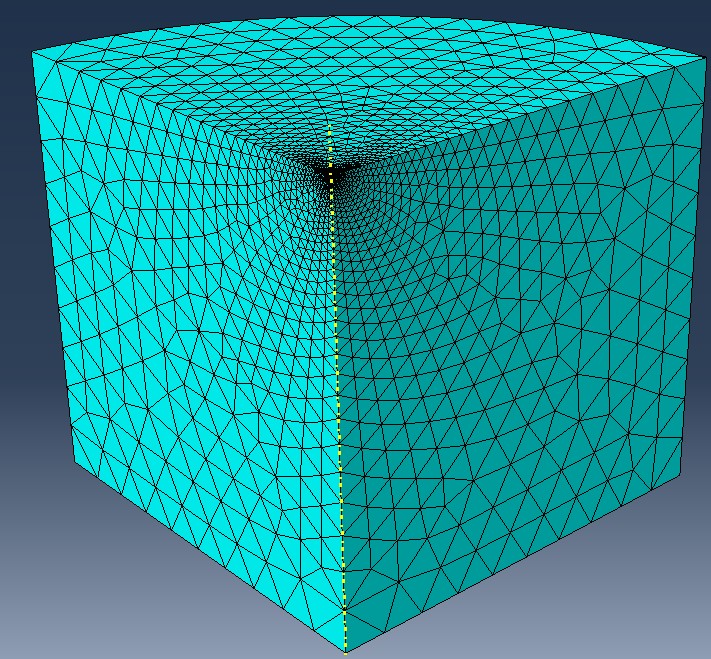
I am studying sharp indentation on a quarter cylinder corner in Abaqus and I am not satisfied with my mesh, which is currently using Tet elements (with edge seeding in the corner). I would like to use bricks (Hex element) and refine the mesh in the contact region. I already tried several solutions with the Bottom-up and "classic" mesh tools. But I don't know how to create fine transitions between each region.

I attached a picture of the partitioned mesh (with zooms on transitions) I would like to obtain.

Does anybody know how to do that ?

Thank you very much

Best,

--
McFly M.
 
Replies continue below

Recommended for you

You could model seperate parts and tie them together, then you can mesh each part with a different mesh density.

Or, you could use bias meshing, where you define a high number of elements in the contact zone and less in the areas you are not so concerned about.

Hope that helps.
 
hello,

My suggestion is also in line with fruton.

I model seperate parts and tie them together and use bias mesh.(mapped mesh)

thanks,
 
A smooth transition between mesh densities is the best option rather than a sudden jump in mesh as this will cause irregularities in the solution at the transition. Use biasing and play around with the various options in CAE for 2D Quad meshing rather than using the structured meshing you have.

Tara


Thank you very much for your answers, I'd better not use different parts to avoid discontinuities but I have really been trying a lot of different options of meshing. But nothing really satisfying.

There must be a way to create the smooth transitions as seen in the attached picture in my first message. Besides, this time I attached a file where we can see the same type of (trapezoidal) elements at the transition between both regions. This figure comes from "Getting Started with ABAQUS/Standard", fig.4-43, "Mesh refined around the hole". I would like to get a similar mesh (with inverted convexity of course).

Any suggestion ?

--
McFly
 
 http://files.engineering.com/getfile.aspx?folder=5b7b9b63-dfaf-4f52-9b8f-14372c04e338&file=refined_hole_4_43.png
Have you tried partitioning the model to achieve what you want?
 
yes, but CAE refuse to mesh my partition with Hex-elements using the classic mesh tool. I also tried Bottom-up mesh (Revolve) but it won't mesh probably because he can't tie each region's mesh due to the gap of density.
 
Here is a running list of questions and comments:
1. Why not axisymmetric? I was under the impression that the loading was non-axisymmetric otherwise I would have suggested it earlier.
2. The part name is cheese are you really modeling the indention of cheese?!?
3. Since you have switched to tets you can use adaptive remeshing to refine the mesh locally based on the loading.
4. Use quadratic Tets or Hex
5. A biased edge seed appears to work well. I tried 20 global and for the 3 edges near indention bias 20 on the peripheral side and 0.5 near contact. (See image)
6. Nonlinear geometry should be used when contact or plasticity are used. It is not turned on in the preload step.
7. What does the preload step do? Is this legacy?

If I get the time I will try running this model. I hope this helps.
download.aspx


Rob Stupplebeen
 
Hi,

Thank you for your help. I already tried a similar mesh but I would really like to mesh with Hex.

To answer your questions
1. Indeed the load could be non-axisymmetric, that is the point of my work.
2. Cheese is just a funny name I gave to my part. (I'm french...)
3. We are not very into adaptative meshing (yet).
4. Yes, I will once I have made the initial verification of my model.
5. Well, thanks, it is good to know.
6. Ok, I will fix this. I am sorry but I don't get what the non linear geometry option does exactly. Has it something to do with large deformation?
7. I study the influence of residual stresses on indentation testing, the point of the preload step is to impose a non-axisymmetric displacement (for the moment it's just a pressure but I will fix this too).

The model is 200 times bigger than the contact region, the purpose was to avoid the boundary effects on the elastic calculations. It could be smaller using plastic.
 
Sorry, I actually didn't try the Bias tool. I will play around this feature and see if I get something satisfying.

Best
 
I finally found a pretty satisfying mesh and managed to achieve very good results with it.

I am now confronted with another problem. I would like to take non-equi biaxial residual stresses into account and study their influence. Therefore I would like to subject the lateral surface of the cylinder to a displacement. I tried 2 solutions :

1) I defined 1 BC (displacement) on the lateral surface (Ux=1/Uz=1)

This is obviously incompatible with the other BCs (symmetry->no normal displacement on faces Z0Y & X0Y). So when I try to run the job I get this kind of message :

"31 nodes have dof on which velocity/displacement/acceleration/base motion etc. constraints are specified simultaneously. The nodes have been identified in node set ErrNodeBCRedundantDof." So I tried another solution :

2) I defined 2 BCs (displacements): one for Ux and the other one for Uz, I also defined 2 analytical fields so that Ux is proportional to X (and Uz to Z). This way there are no conflict between symmetry BCs and "load" BCs.

But still I get the same message. It seems that there is still a conflict in the fact that I impose the same the constraint twice at the same place.

Is there a way to avoid this ?

(I already tried to impose a pressure on the lateral surface and it worked but that is not the point of my study, unfortunately...)

--
MF
 
Status
Not open for further replies.

Part and Inventory Search

Sponsor

Back
Top