tectactoe
Mechanical
- Apr 9, 2024
- 2
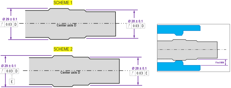
The picture below shows a gray shaft with multiple stepped diameters. It will go inside of a blue tube (that also has stepped diameters).
The largest diameter on the gray shaft is the locating diameter to the blue tube. I care about the minimum gap between the smaller gray diameter (to the inner blue diameter).
In SCHEME 1, the two gray diameters (i.e., the locating, and the secondary) both have a runout tolerance to the same reference datum (overall part datum axis "D").
In SCHEME 2, the locating gray diameter has the same runout tolerance to part axis D, but is also defined itself as a new datum axis, E. Then, the secondary diameter's runout is instead referenced to this locating diameter axis, E.
Simple gut/eye check tells me that the stack condition should be improved with SCHEME 2 (larger min value).
I think this logically makes sense, too, because the gap is smallest when the two gray diameters are maximally opposed (that is, when their high spots of runout are diametrically opposite). In SCHEME 1, since they reference the same datum axis, the runouts CAN be totally opposed by the added runout amounts. Since SCHEME 2 kind of mandates that the secondary diameter "moves with" the locating diameter, the condition should improve.
The problem is, I cannot figure out how to rectify this in a tolerance stack sheet. Nor can I really find a way to justify it with tolerance stack / GD&T rules.
I feel like there might be something I'm overlooking - anyone have any thoughts/ideas?