Continue to Site

Eng-Tips is the largest engineering community on the Internet

Intelligent Work Forums for Engineering Professionals

  • Congratulations KootK on being selected by the Eng-Tips community for having the most helpful posts in the forums last week. Way to Go!

How would you design this Glulam beam? 2

Status
Not open for further replies.

ThomasH

Structural
Feb 6, 2003
1,176
Hello

I am working with something that has me wondering how others would view this issue.
It concerns the glulam beam that you can see (simplified) in the figure bellow. It is a simply supported beam with an additional glulam "column" from 1 to 2. The blue lines are steel bars slightly prestressing the truss.
Figure_1_l86x1s.png


The load on the beam will result in tension in the steel and compression in the column. My impression from looking in different documents is that this structure is usually analyzed using beams or other line elements. But due to the circumstances I am using plate elements för the top beam. The figure is a simplification of reality but the top beam is 215 mm thick and 1.6 m high. What happens is that it buckles out of plane at location 2. And if I use non-linear analysis with initial imperfections I get a significant moment in the connection at 1. That of cource depends on the size of the imperfections.

My questioon is, how would you approach this structure? The reason I ask is because I can't see non-linear FEM-analysis as a typical design method. And I don't see how you can find this effect without it.

As always, ideas are appreciated.

Thomas
 
Replies continue below

Recommended for you

Or wait, that is the connection at the ends. KootK approved....
 
Agent... I really like that framing...

Rather than think climate change and the corona virus as science, think of it as the wrath of God. Feel any better?

-Dik
 

Can't reach the link, but the AISC had a really good article on this about 40 years back.

Rather than think climate change and the corona virus as science, think of it as the wrath of God. Feel any better?

-Dik
 
If the steel element is not externally tensioned, and the stud is not rigidly attached, the wood beam will lose the middle support (due to slip), if instability starts at point 1 or 2. If both points are rigidly connected, the beam will rotate/twist when instability occurs. This is a passive support system.

If the steel element is pre-tensioned, and both joints are rigidly connected, both of the buckling strength of the stud and the wood beam need to be investigated. If both joints are not rigidly connected, then loss of support due to slip can occur.

I wouldn't relying on computer model to automatically addresses the loss of support situation.
 
ThomasH:
The GluLam beam is 8.5” wide and 5’ - 3” deep, you say; how long is the span, what’s the loading, and how is framed and braced into the structure. There is nothing like an ill proportioned sketch to confuse the real issues. Your beam must be about 45’ long and the center post is 7 or 8’ tall, per your sketch, correct? That’s a lot of harp in the bottom rods, and that post length will give you stability problems with the connections and the post. That’s a pretty deep beam, it is kinda hard to imagine that the harped rods are going to improve things, as much as they might on a shallower beam. You would be surprised at how a well proportioned sketch helps an experienced engineer make prelim. determinations on a problem like this.

There is probably plenty of depth within that beam for the harping. The way, a common way, to detail these beams is with the harped rods on either side of the beam, and the end reaction bearing pls. fitted around the butt end of the GluLam about 2/3 or 3/4 of the way up the depth of the beam. These pls. are inclined to be perpendicular to the axis of the rods, for nuts and washers. Then, there might be two harp points at about the third points on the span length. These turning points for the rods are only a short distance below the bottom of the GluLam beam, maybe only 8”-12” for some weldment, a base/bearing pl. and a 6” or 8” dia. piece of heavy pipe about 16” long, for the harped rods to bend around and bear on, in saddles of some sort. This pipe is horiz. and perpendicular to the vert. plane of the GluLam. Thus, the long post and its moment and stability problems go away. You do still have potential beam stability issues to deal with and a sizeable compressive load on the now beam/column from the rod reactions at the beam ends. Threaded stl. rods are best because tendons or wire rope require too much take-up (stretch/elongation) to bring them into play. Then, threaded rods, nuts washers, turnbuckles, pinned end shackles and the like make up the hardware. You can strain gage some of the rods; make some calc. about how much vert. force will lift the beam 1” and then back calc. for the rod forces; snug the rods up until you do start lifting the beam (take most of the slack out of the system), then some turn-of-the-nut method to make a judgement about the loads/elongations in the rods. Only the stain gages give you a reasonably accurate reading.
 
Wouldn't be beam on elastic support a simpler solution? If doable, a brace at point 1 is preferred.
 
I would design as a truss, and brace it so it can’t buckle or roll over.

At uni we had competition to build truss bridges from popsicle sticks. This simple truss was a common and relatively successful design. Not the most efficient, but simple and effective. You’d build two and then cross brace them together, like road bridges.

Most of the little bridges failed by buckling of top chords, or the whole thing rolling over.
 
Hello again,

First I would like to thank you for your input. I appreciate it even if I haven't participated in the discussion frequently. The reason I started the thread was because I wanted to know how you would approach the design of the structure. My work is to figure out why it failed. The faliure was not spectacular and luckily only material damage occured, but still, why did it happen?

When you know that it failed, of course that changes your approach to the problem and I wanted your unbiased opinion. Hence the "misdirection", I hope you forgive me for this [smile].

The structure that failed was not identical to the figure that I provided but the principle is the same. You have a glulam beam that is relatively slender. You add a post at the middle, or two posts along the beams length to reduce the span of the beam since the posts will act as supports. And the steel rods create a support for the posts.

Now I have an additional question. Are there any manuals or specific codes in North-America for this type of glulam structures? I have information from Europe but I would like to compare methods if possible.

Thank you

Thomas
 
I missed something... I didn't know that it had failed. Can you describe the failure? Lateral buckling of the glulam? instability of the post? Was it braced? How?

Rather than think climate change and the corona virus as science, think of it as the wrath of God. Feel any better?

-Dik
 
OP said:
20 Nov 20 20:59
Sorry, my explanation was erroneous.

The structure buckles out of plane at position 1. Position 2 is restrained out of plane. So the stability is dependant on moment capacity in pos 1.
The structure becomes very sensityve to imperfections, hence the thought about non-linear analysis.
 
I'm going out on a limb and guessing this is about a failure in Kiruna, Sweden. There's a preliminary report on the failure by a university. unfortunately just in Swedish.


The failure is also being investigated by The Swedish Accident Investigation Authority (SHK), but no report is finalized. The procedure can be followed at link below, in English.


Sorry again... I thought it was his model, not a real structure.

Rather than think climate change and the corona virus as science, think of it as the wrath of God. Feel any better?

-Dik
 
Dik,

It is the op's analytical model, not a real structure, I believe.
 
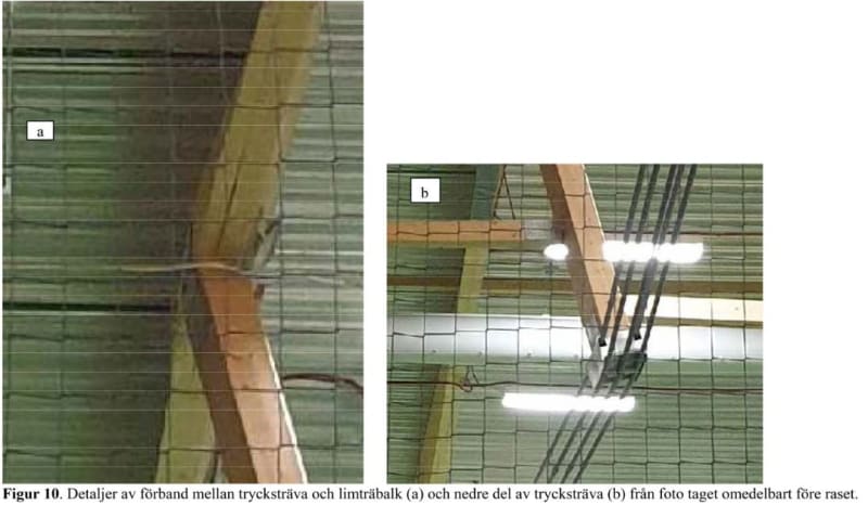
Oof. Well, ThomasH is Denmark, so it's certainly plausible that he'd be looking into a failure in Sweden. Sadly I'm 4 generations from Sweden, and posses none of the language. Picture's worth a thousand words though:

Capture_nwcfad.jpg
 
I know this is a later entry, but while looking for something else came across this post. To the original OP Thomas. I hope you've found the assistance you needed in your review and analysis. To answer your question, 'are there US codes addressing these structures with relation to Glulams'-No, I do not believe there is. The information you will find here are based upon glulam repairs, not bow string truss methodologies since you do not use such large glulam members intended with 100% flexural capacity intention. One company uses a technique exactly as described by dhenger above and the other using horizontal post-tensioned cables stanchioned very close to the bottom laminates,...as if to act as additional laminates for the beam and only slightly effecting the neutral axis of the retrofit. The later design repair technique and configuration of course not related to your post.

Thus agreed with a tough design repair challenge using even a FEM model with the intent on modeling the true structure to resist all loads as if it were a bowstring truss. In doing so, the forces in the rods are incredibly high. Thus begins the attempt to deepen the central strut to increase the moment couple which intern decreases the forces in the rod. However this increase the vertical component forces in the strut due to the geometry as well as mentioned by all above, adding to the lateral instability at the both the bottom of the strut and at the top of the strut at the connection at the glulam. You've essentially now an unbraced column continuous beam over a column cap, it needs to be braced at that location or gusseted somehow in the form of a saddle or the beam itself will require bracing laterally within a reasonable distance from the concentrated load say 1/2 the glb depth or so. But truly, the tension connection at the bottom of the struct should be braced as well. With any appreciable out of plane movement at the bottom of the strut, I'm not sure any shallow connection at the glulam would resist the induced moment forces. From the photo, it would appear although this obvious, the strut connection rotated, split the member, crushing the parallel fibers in the process. A deeper saddle connection with through bolts higher on the beam may have helped this situation if a beam brace at that location was not feasible or desirable. Or a full wrapping saddle even better, no through bolts. I believe this style of repair, by nature of a now lower neutral axis, theoretically reduces the tension in the bottom plys of the glb but puts more of the plys into compression than before, granted at reduced measure but how does this effect unbraced lengths effects? Thus also the importance of addressing the lateral braced lengths especially of deeper glulam beams.

Per dhenger's post again, most of these 'designs' with such large glulams are 'repairs'. Thus no representing codes or design manuals addressing how to design these structures as original structures which are so unreasonably balanced. They frankly would never be considered economical and the problems everyone has aforementioned bring reason to why this is so. Actual tension in the steel rods hard to quantify in the field without strain gauges, special inspection and qualified crews. Enough torsion is typically applied to the rods in order to resolve deal load deflection issues. Calculating the load required to create a 1" deflection in the beam can perhaps estimate how much load is actually in the rods as well as help you determine how much strength you have given back to the beam, increasing its capacity by some measure, hopefully to the point that includes any remaining dead load and the member design live loading.

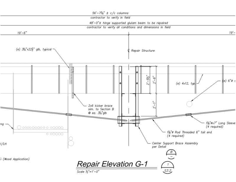
A similar repair image included below for what sounds like a smaller glulam beam repair: The center strut connection shown only. This repair connection by nature of the saddling angle extensions resolves some moment which may occur at the strut connection to the beam. Additional lateral bracing was added to the bottom of the glb at every sub-girder connection along its length.

S3._G-1_Repair_Elevation_hwqb7o.png
 
Status
Not open for further replies.

Part and Inventory Search

Sponsor