Continue to Site

Eng-Tips is the largest engineering community on the Internet

Intelligent Work Forums for Engineering Professionals

  • Congratulations KootK on being selected by the Eng-Tips community for having the most helpful posts in the forums last week. Way to Go!

HX Design

Status
Not open for further replies.

SHD_

Chemical
Feb 10, 2020
5
Hi!

I'm currently in the process of designing a heat exchanger (as part of a large process). I know the desired inlet and outlet temperatures and the flow rates. Ethylene gas are the both streams being heated/cooled.

I am struggling to understand the difference between Q=m.c.dT and Q=U.A.dT and what cp values to use when (as I'm aware that cp values of gas will change with temperature).

Thank you in advance for your time :)
 
Replies continue below

Recommended for you

Based off your post, I'm assuming you're just trying to determine some rough numbers to provide to a 3rd party vendor so they fully size/design the heat exchanger? I would grab a copy of Perry's Chemical Handbook as the relevant chapters have some good information on typical U values to use depending on the tube/shell configuration and other parameters.

Since you're working on a process (new? existing), you should know the mass flow required by the process, the fluid parameters, and determine Q. If you have preliminary U & A values from vendors or from Perry's, that can help you determine which exchanger design/size will be best suited for the process needs by comparing to the Q you determined.

Note there are other factors like fouling factors that come into play.
 
I don't know why you would need more than the two mass flow rates, two inlet temps, and the Q (or outlet temps) to give to designers. The only other issues are piping configurations and desired MoC. Let the fabricators design it and propose this back to you. Yes, different firms will design different sized HX for this, but they should each be able to defend their designs.

= = = = = = = = = = = = = = = = = = = =
P.E. Metallurgy
 
Thank you for your replies. I should have previously mentioned that I am a final year student, working on my design project. I feel that the mechanical design element will be rather easy, assuming values found in literature. The most basic step of determining Q is what I am struggling with. Could it be that my flow rates are not sufficient to complete this amount of heat transfer?

I have two inlet temperatures of 25, 110 and outlet temperatures of 70 (all degree celsius). My flow rate of hot stream is 635kg/hr and cold stream 12077kg/hr.

Thanks again!
 
This is basic HX design.
Do the Qs match each other? Just use an average c, as long as there is no phase change it will be close enough.
How close of an approach is realistic? They will not be the same temp.


= = = = = = = = = = = = = = = = = = = =
P.E. Metallurgy
 
Seems to me that you are confusing yourself because it looks like you didn't pay attention in class.

Your first equation describes the mass heat transfer rate, which you use to determine your Q, given that you already know your flow and inlet and outlet temperatures. Your second equation describes the basics of what your HX physically requires, given a heat transfer coefficient from the hot to cold sides and your known heat flow required.

TTFN (ta ta for now)
I can do absolutely anything. I'm an expert! faq731-376 forum1529 Entire Forum list
 
Thanks for your replies. My Q values are very far off, this is what's causing me the trouble. I have been determining cp values from the ideal gas heat capacity equation found in Chem Eng Design by Sinnot and Towler.

What do you mean by my data is inconsistent please? The mass balance across my whole process have given me the mass flow rate and temperatures, this heat exchanger is in the recycle stream of a reactor.

Thank you
 
You say outlet temperature"s" = 70C, meaning that both hold side and cold side? Is this a requirement imposed by your instructor? If so, the only way this can work is if you have a counterflow configuration, i.e., inlet of the hot side is adjacent to the outlet of the cold side, and vice-versa. This would give you a deltaT of 40C on the hot side inlet, and 45C on the hot side outlet.

TTFN (ta ta for now)
I can do absolutely anything. I'm an expert! faq731-376 forum1529 Entire Forum list
 
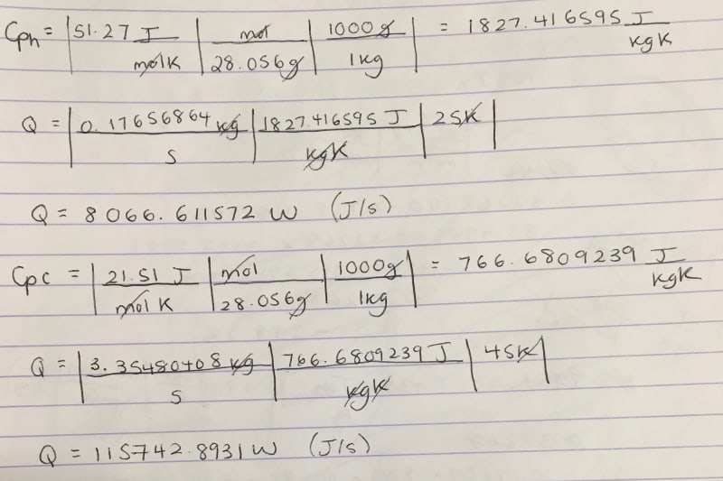
IMG_4941_v8ozs5.jpg


So this is what I get using inlet T of 25, 110 an outlet T of 70 and 85. I believed that the outlet T could be calculated by equating the q values but that gives me a negative value of T so I used 85 as a trial. The values are very different. I honestly thought this would be the easiest step of all but it seems I have no knowledge when it comes to heat transfer!

Thanks again for all your help!
 
You appear to be randomly plugging and chugging with no understanding of the basics of a heat exchanger. Where is the heat exchanger in all of your calculations? Why are you ignoring conservation of energy?

Did you take thermodynamics?

TTFN (ta ta for now)
I can do absolutely anything. I'm an expert! faq731-376 forum1529 Entire Forum list
 
SHD -

At one time during our academic life, we were all at the same place that you're at now. So there's no criticism here. Q=MCdT calculates the heat gained by raising the temperature of a fixed quantity of fluid. Heat exchangers are designed based on heat transfer rates (Q=UAdT).

On the internet and in books, you'll find plenty of basic guidance for understanding the calculations that go into designing a heat exchanger. Once you've grasped that, you can find plenty of further guidance (same sources) for how to choose the right type of exchanger for a given application, and how to optimize the effectiveness and cost by manipulating the geometry and the internal design of the exchanger.

It's obvious from your questions that you're new at this topic and that there a lot of foundational knowledge you need to build. This forum isn't the place for that. You need to do that on your own.
 
SHD,

You calculated the heat gained/lost by each individual stream (Q = mdot * Cp * dT), and found they are significantly different than each other. This tells you that the value you randomly chose is not the correct one. It also tells you that the approach you used is wrong, as is your understanding of the thermodynamics at work. That makes me a bit concerned.

Heat gained by the cold stream is equal to the heat lost by the hot stream (minus loss to atmosphere). So if the 110 C stream is taken to 70C, the other stream would be:

635 * Cphot * (110-70) = 12,077 * Cpcold * (Tf-25). Solve for Tf.

The hot stream doesn't have enough enthalpy to heat the cold stream up to 70 C due to the low mass flow rate, so the above approach is the only one that makes sense.

That's only the first step on Hx design. You have a Q, but now need to determine the other heat exchanger parameters. Q = U*A*dTlm is the governing equation for a heat exchanger. I do not know how in-depth you are expected to go on heat exchanger design. I doubt they need baffle spacing, TEMA type, etc. Finding a organic gas to organic gas U is probably good enough for the design. Rigorous design would take into account pressure and temperature effects on viscosity, which effect the local Nusselt/Prandtl number. That's something for a computer to solve, not a college senior.

Edit: Equation edited for clarity.
 
Thank you so much! I truly appreciate your time. Yes there's an overwhelming amount of information on heat exchangers of course, I shall get to studying further!

I think the mechanical design and simulations will all be more straight forward once I get my numbers right, thanks again!
 
Status
Not open for further replies.

Part and Inventory Search

Sponsor