Eng-Tips is the largest engineering community on the Internet

Intelligent Work Forums for Engineering Professionals

  • Congratulations waross on being selected by the Eng-Tips community for having the most helpful posts in the forums last week. Way to Go!

Hydraulic Steering Schematic explained

Status
Not open for further replies.

Andymator

Student
Feb 17, 2024
3
SE
Hello
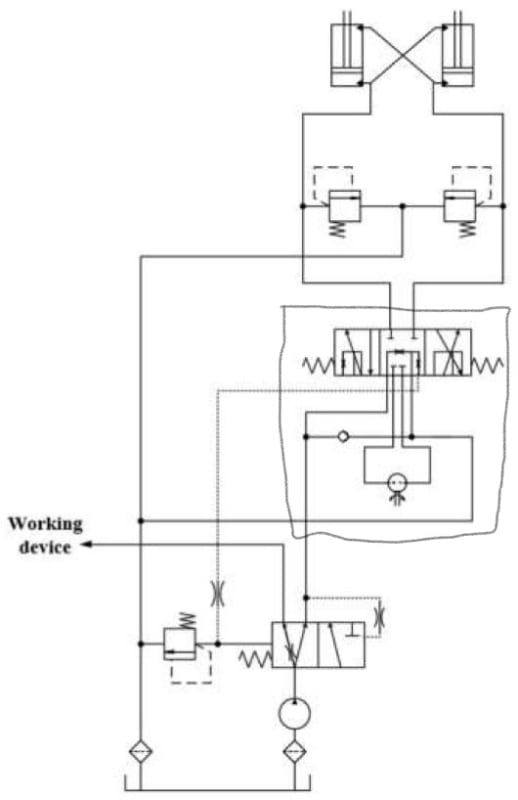
I need to know how this system works so that I can teach it to my students. I am a high school teacher in Sweden and the hydraulics part of the course has always been my weekest. Can someone please explain this schematic to me? What is most confusing to me is that their are actuators at the top, but also an arrow pointing to "Working Device". Arent the actuators the ones usually doing the work?
/David
 
 https://files.engineering.com/getfile.aspx?folder=87f1880f-b213-449c-b8ef-7761765477ba&file=Hydraulisk_styrning.jpg
Replies continue below

Recommended for you

The "working device" might be an auxiliary load that gets shed whenever there's a demand on the main system.

I don't think the drawing of the valve in the middle of the image is complete - there's nothing to indicate how the valve is actuated and, while the central position shows what happens to five inlet ports, the other positions only show four of them.

A.
 
Thank you for the answer. Too bad I have this image to some of my students with the task of finding out and explaining how a hydraulic steering system can work. Could you point be to another schematic image that is better for that purpose? Thanks!
 
It appears to me the Working Device is an auxiliary device, sometimes called PTO (Power Take-Off), such as a mowing attachment or other attachment. What seems to be missing is the return line - fluid goes out and never seems to come back.

Compare to
Notice valve EC16-42 doesn't have the restrictions yours does; it has the bars above and below indicating a leak path so that the as the valve moves from position to position it varies the amount of flow available to each; in the position shown steering gets the majority flow, but can adjust to giving Auxiliary Functions priority.

This also has not obvious Auxilary return line, which is a bit odd, but I don't do tractors.

The steering valve is a bit better explained - same thing with the bars - continuous variation between steering right and left, but note the indication that this is a rotary valve rather than one that shifts linearly.
 
I see. I wish I understood everything better. I hope that comes with more experience :)

I have tried to write something about how the system in my original image works. Could you check it for errors and maybe correct it? Im having the lesson tomorrow...

The fluid is controlled or affected by a filter before it reaches the pump. Above the pump, there is a control valve with 3 ports and 2 positions. In the control valve's left position, the fluid goes both to the "Working device" and to a second control valve which has 4 ports and 3 positions. In the extreme positions, fluid goes into one cylinder and out of the other back to the tank. In the middle position, nothing goes to the cylinders. Presumably, everything from the lower valve then goes to the "Working device".
 
This is a primitive priority flow control system. When I say primitive, I mean that there are much better methods available that give better steering control and a better experience for the driver.

There is a suction strainer on the pump inlet.

The "working device" can be anything. Let's just say it's an actuator of some sort.

With no steering input, the pressure differential on the priority flow control valve will move the valve to the left and all pump flow will go the "working device".

When there is steering input via the steering wheel, the dotted line (pilot pressure) sees higher pressure and that is fed to the end of the priority valve and it pushes it back to the right to give priority flow to the steering system.

The pressure in the steering system is limited by the relief valve that controls the pilot pressure.

It will be all or nothing, a bit clunky on the steering as the priority valve is not proportional and there isn't much pilot damping.

There are relief valves on the steering cylinders, to prevent pressure spikes caused by external loads leaning on or hitting the wheels.

The steering input and the control valve are all part of the same steering unit, as per the image below.

InkedHydraulisk_styrning_LI-x_bakowp.jpg
 
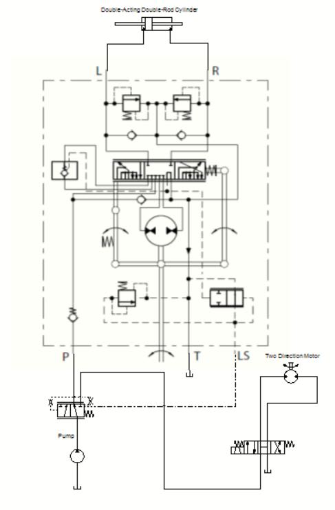
A modern steering might look something like this...

Steering_jwk3rw.jpg


Of course, so pressure relief are missing from the system, but you get the idea.
 
Status
Not open for further replies.

Part and Inventory Search

Sponsor

Back
Top