Continue to Site

Eng-Tips is the largest engineering community on the Internet

Intelligent Work Forums for Engineering Professionals

  • Congratulations SSS148 on being selected by the Eng-Tips community for having the most helpful posts in the forums last week. Way to Go!

I am building a pressure vessel mad 2

Status
Not open for further replies.

Jack Oswald

Aerospace
Nov 23, 2018
9
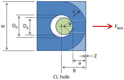
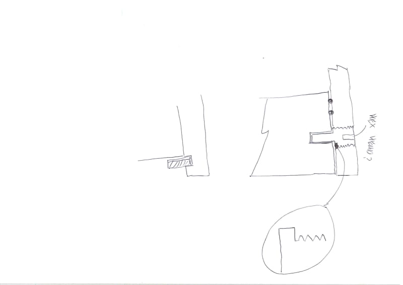
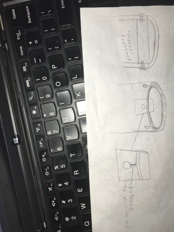
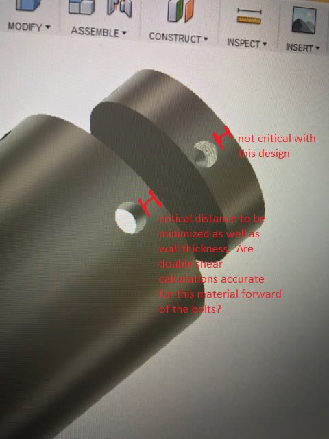
I am building a pressure vessel made of a round tube with two disk closures; the closures are retained by 1/4" bolts. I would like to minimize the distance necessary to install the retention bolts from the end of the tube. Would you calculate this distance with simple average double shear, or some compression/ single shear calculations because of the rounded surface of the bolts?
 
Replies continue below

Recommended for you

Impossible to say without any idea of the exact arrangement. Sketch?

Regards,

Mike

The problem with sloppy work is that the supply FAR EXCEEDS the demand
 
"I would like to minimize the distance necessary to install the retention bolts from the end of the tube." ... huh ??

are the 1/4" bolts working in tension or shear ?? ie is the bolt axis aligned to the radial direction, around the tube, or normal to the "closure disc" ?

"because of the rounded surface of the bolts" ... huh ??

another day in paradise, or is paradise one day closer ?
 
IMG_3277_avbdat.jpg


Not sure if that upload will go through properly ^

The bolts are working entirely in shear arranged radially about the tube. Would like a nice way to calculate the amount of tube material needed to keep the bolts retained. They should be placed as close as possible to the end of the tube meaning that the axial stresses on the tube material upwards of the pressure and bolts becomes critical.

I'll get a better description up in a minute with some CAD captures; sorry for the poor initial explanation.
 
If you have noticed, no one builds anything called a pressure vessel like this. You are asking for help with a design with a huge chance of maiming or killing people.
 
Conservatively, you consider shear out of the minimum edge distance, as your red markup shows. Note much of your text is unreadable. More accurately a double shear plane is taken as, as I recall, 30 deg or so either way off the longitudinal CL. No doubt one of the aircraft guys can confirm.

Regards,

Mike

The problem with sloppy work is that the supply FAR EXCEEDS the demand
 
@3DDave This configuration is for a solid rocket motor propellant characterization test; the "pressure vessel" is really the combustion chambers which operates at 1500 psi. Obviously, there are seals and a nozzle on one end; didn't think it was necessary to go into detail about the whole project. This setup is standard for all sizes of preliminary tests of this kind. I've attached a photo of our last motor designed for 10,000 lbf-s.
 
 https://files.engineering.com/getfile.aspx?folder=3624b4d6-e6b8-42e4-a89d-21f1825d25fc&file=Cross-Section_Flight_Motor.png
@SnTMan Mike, thanks for the response. My fault, should have uploaded higher quality. To confirm, you're referring to double shear of the two planes shown in this image?
Jack
Close_Up_jxjmep.png
 
@SnTMan We can definitely go with shear at that minimum edge distance as an appropriate approximation for the worst case scenario. I have always designed this using rule of thumbs etc. would be nice to be able to optimize. Any literature you know of on the topic? Really appreciate the input.

Jack
 
The caution in recommending engineering solutions for anything someone calls a "pressure vessel" is that one of the reasons there are American engineering standards is pressure vessels exploding and killing people. At least that's the reason ASME exists. In fact, one blew up just in the past year or so and killed a couple of people nearly 600 feet away because it rocketed out of one building and crashed through the roof of another.

It is fairly easy to set up a hydrostatic test in a water tank and crank the internal pressure up to see the point it fails. I suppose if it doesn't then shave off some metal and give it another try until it does or crank up the pressure to see how much margin there is. Keeping it submerged prevents pinhole leaks from getting to people and injuring them. Much better than calculations that are depend on simplifications.

Tearout calculations usually assume that no threads are in shear or bearing. Without match-reaming close-fit fasteners it is likely that only two of the four fasteners will carry most of the load.

I see I'm not the only one considering hydrostatic testing ". In the professional aerospace world, room temperature hydrostatic test results are extrapolated to operational conditions by detailed thermo-mechanical modeling and then instrumented testing is conducted to verify the design. This is well beyond the capabilities of the hobbyist."
 
@3DDave That's definitely a fair point with regards to pressure vessels, something us in the amateur rocketry community have enormous respect for. We test our motors at a professional facility in the Mojave with members present in a steel reinforced blockhouse. I am of course, looking for a simplification, but I plan to apply a large safety factor to the design; we design our motors to have the forward closure fail (retention bolts fail in shear) should the pressure reach unacceptable limits. Right now, we're looking at reamed bolts and adding a conservative safety factor to the single shear Mike alluded to.
 
Jack Oswald, the two planes are more like 45 deg off longitudinal CL, and parallel to it. My reference is for design of lifting lugs from ASME BTH-1 2005 (Design of Below-the-Hook Lifting Devices), but the same concept should apply. I am sure there are any number of references showing pretty much the same.

Regards & keep your head down :)

Mike

The problem with sloppy work is that the supply FAR EXCEEDS the demand
 
Why not use a blind flange at the end of the tube? The bolts would then be in tension as would be desired for a pressure vessel.
 
Here's a picture:
simplified-lug-02_fstzzy.png


The problem with sloppy work is that the supply FAR EXCEEDS the demand
 
@Ron That is common with larger motors, but for smaller diameters like ours, axial retention really isn't as feasible as radial on the nozzle end.
 
@SnTMan Great, thanks a lot. That's just the reference I needed.

Appreciate it,

Jack
 
I've been thinking about this and think you might be better off doing your bolt the other way around.

I.e. make the threaded part in the outer cylinder and then machine down the lower section into a tight pin. see below.

Also this is similar to a commercial flange connection device called a "Lok-O ring" flange kit made by TDW. This is good for pressures up to 100 bar at 6 inch. The new version actually uses the second option I put in below with moveable "leaves". The older version is the second link below. I'm a great believer that you should use things developed, tested and certified by others...

]


That way you won't have the same issue as having a slightly small pin inside a hole tearing out and can ensure that the failure is in shear in the pin.

You might need a few more pins, but I think this is a much better and more easily designed system.

Not sure why you want to reduce the end distance? Anything less than 1D of the hole will cause issues I think if you do it as per the original design.

PV_end_connection_xzme2t.jpg


Remember - More details = better answers
Also: If you get a response it's polite to respond to it.
 
beside shear stress, don't forget bearing calculations
 
I'd've thought that having the bolts in shear (reacting the end-cap load) was better than using them in tension (per LittleInch's suggestion). Yes, there'll also be a tension load (from pressure) but probably not much (as pressure is reacted internally by hoop stress). I'd worry about building this endcap to fit "exactly" into the PV shell/cylinder. Other's have already informed you about the "shear tear-out" issue that initially you thought wasn't a problem. You're relying on the clamp up pressure to seal the PV ... ? no O-rings ??

as a rocket, you can probably improve the end-cap thickness (to save weight). It need to be thick at the edge (for the heli-coil) but probably doesn't need to be so thick in the middle. I assume you're CSK-ing the screws ... thickness of the cylinder wall is possibly a design issue (is it a fatigue concern ?)
 
Status
Not open for further replies.

Part and Inventory Search

Sponsor