Continue to Site

Eng-Tips is the largest engineering community on the Internet

Intelligent Work Forums for Engineering Professionals

  • Congratulations KootK on being selected by the Eng-Tips community for having the most helpful posts in the forums last week. Way to Go!

I beam or box beam for crane long travel, which is better? 11

Status
Not open for further replies.

edison123

Electrical
Oct 23, 2002
4,454
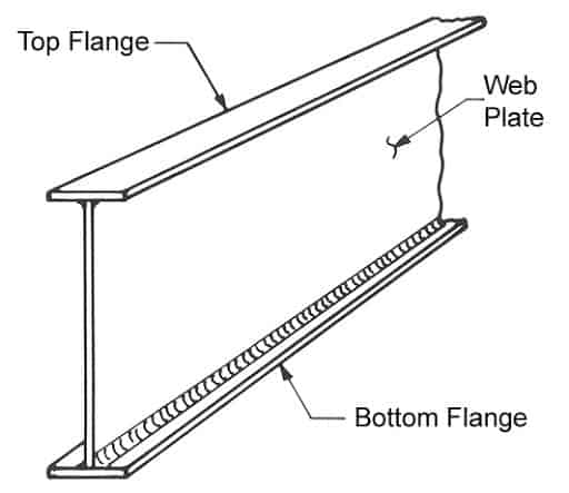
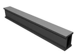
For a crane long travel along a factory length, in terms of load carrying and resisting torsion while the crane moves, is a I beam of hxw with one vertical web of thickness t is better than a box beam of same hxw with two vertical webs of thickness t each as shown below? Crane supplier claims I beam is better. Both are fabricated from structural steel.
Parts-of-an-I-Beam_htcmux.jpg


box-beams-250x250_pezfzk.jpg


Muthu
 
Replies continue below

Recommended for you

1 fatigue concerns ? please explain why lower stresses produce fatigue concerns ? I'm assuming lower loads mean lower stresses, of course they could mean the same stress, but then the same question. I'd've thought that a stiffer beam would've been "better" ?

3 yes, I get stiffeners as load distributors. And "maintain the stability of the cross section" in both web shear buckling and cap lateral bending/buckling.

"Hoffen wir mal, dass alles gut geht !"
General Paulus, Nov 1942, outside Stalingrad after the launch of Operation Uranus.
 
please explain why lower stresses produce fatigue concerns ?

The fatigue concerns arise from the welds needed for transverse stiffeners. A beam with fillet welds perpendicular to the direction of stress has a much lower fatigue resistance; about half that of a beam with only longitudinally welded attachments.

Rod Smith, P.E., The artist formerly known as HotRod10
 
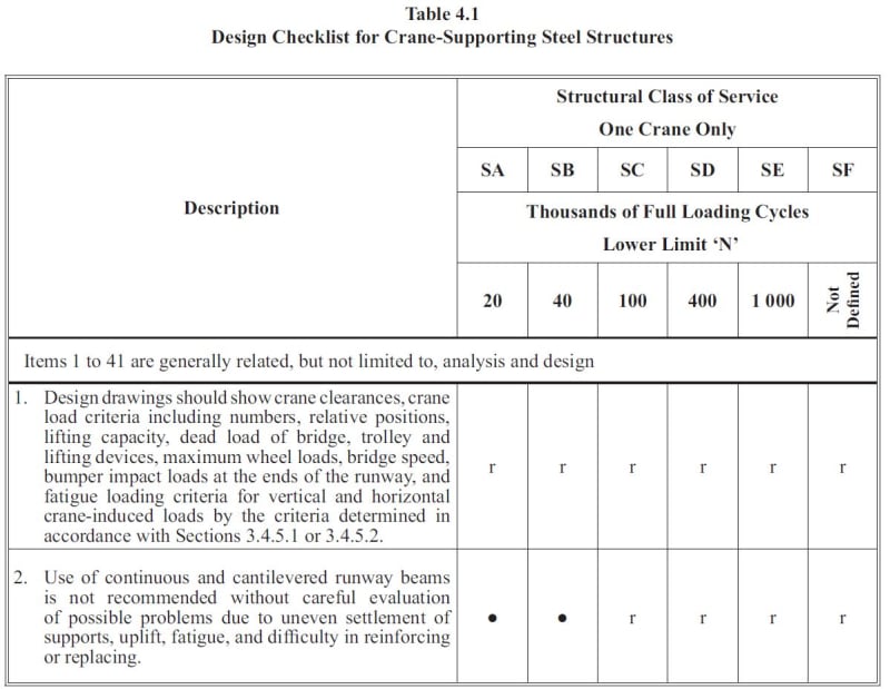
From the CISC Crane manual, they mention use of continuous crane beams with a caveat. From a design point of view, the stress caused in the bottom flange of a +ve moment on a simple span and the -ve moment over the support is 77% approx, and introduces these other issues. Unless for very light loads or infrequent usage, I've always gone simple span. Others may have other comments.

Clipboard01_oowzyl.jpg


So strange to see the singularity approaching while the entire planet is rapidly turning into a hellscape. -John Coates

-Dik
 
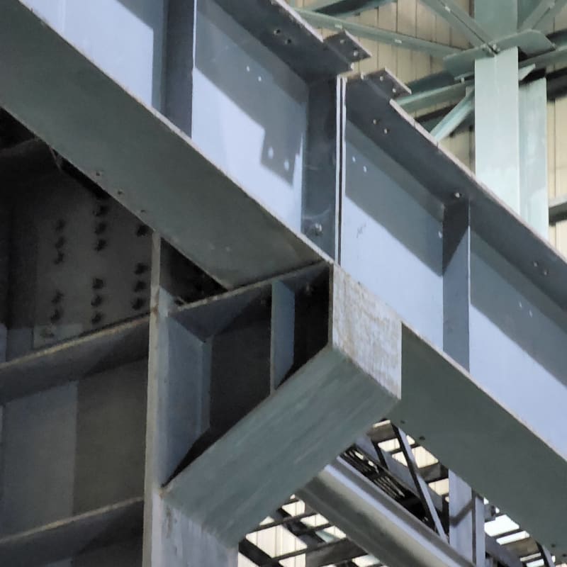
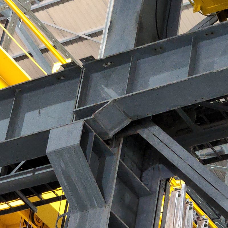
Below are pics of the runway beam of a 105 ton EOT in a nearby power station where the stiffeners are welded to the top and bottom flanges and for the entire web height. These photos were personally taken by my team.

20220729_111540_rekd6r.jpg


20220729_112010_sbjjee.jpg


Muthu
 
edison... just because you can, doen't necessarily mean that you have to. [pipe]

So strange to see the singularity approaching while the entire planet is rapidly turning into a hellscape. -John Coates

-Dik
 
but it also doesn't mean that you Shouldn't. It looks to be personal preference.

The nuance could well be that there are details in the design welded to the flanges that are not obvious and if not incorporated (by an unaware designer) could be dangerous.

And dik prefers to use web stiffeners to distribute load into the web (and less as panel breakers).

"Hoffen wir mal, dass alles gut geht !"
General Paulus, Nov 1942, outside Stalingrad after the launch of Operation Uranus.
 
Looks like you have most of the major things worked out.

I'll just reiterate my previous statement that we've found it's more economical in today's environment to thicken the web to eliminate web stiffeners for shear. It might be something to consider for the runway beam design, since the loading conditions are fairly similar.

Rod Smith, P.E., The artist formerly known as HotRod10
 
I suspect that material is still more expensive than labor in India, which justifies using stiffeners to save on steel - not so in e.g., the US or most of Europe.

Edison: the detail does not make much sense. Your supplier has either misunderstood the purpose of vertical stiffeners or not thought about the details in the first place. There is research on this subject, and it clearly shows that cracking and fatigue is amplified in welded joints connected to the flanges. Those types of connections also create a vertical stress in the stiffener and the flange and depending on loading conditions, also lateral stresses. Beams are usually designed with dimension reduction models that incorporate only stresses acting in the longitudinal direction (normal stress sigma_xx and shear stress tau_xy=tau_yx); not even using shell elements will save you from trouble, since they do not include through-thickness stresses and deformations.
 
I suspect that material is still more expensive than labor in India, which justifies using stiffeners to save on steel

Man, I gotta remember to look at those country codes in the profiles. I keep forgetting the ET membership is worldwide. Yep, you're most likely correct, centondollar.

I'll agree with you on welding to the flanges, also. Welding to the flanges doesn't help the shear capacity. If they help keep the top flange from twisting, I can understand fitting them tight to the top flange, although to avoid severe stress risers in the flange-to-web welds at the stiffeners, we always clip an inch or more off the inside corner of the stiffener and if we weld them to the flange (when used as connection plates for diaphragms), we hold the weld back 1/4" from the clipped edge.

Rod Smith, P.E., The artist formerly known as HotRod10
 
different companies solve the same problem differently ... neither are wrong (if they both have good service experience).

When you get a moment have a look at the Learjet cabin door (any model) and the Hs125 cabin door. One company had a major fatigue failure that scarred their psyche and the other learnt "with enough Aluminium you can fix just about anything". On the Learjet the door is outlined on the fuselage (with square corners).

OIP_tel0rj.jpg
R_vhhbxk.jpg


"Hoffen wir mal, dass alles gut geht !"
General Paulus, Nov 1942, outside Stalingrad after the launch of Operation Uranus.
 
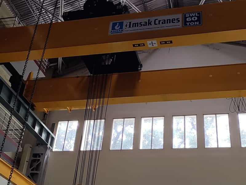
Update: The 45 ft span, 40 ft lift, 60 ton EOT crane has been designed, built, installed and commissioned successfully in my motor repair shop all within 10 weeks. The total weight of EOT crane is about 27 tons. The picture showing the crab and the LT beam is below. As discussed, I insisted on a cap channel on the LT beams top to arrest lateral sway. The maximum center deflection of bridge beams was 9 mm with 63 tons at the middle of the span. The crane supplier is well experienced with a great infrastructure and addressed all my concerns very well.

Thanks again for all your tips.

EEW_60_ton_EOT_v8obfj.jpg


Muthu
 
Status
Not open for further replies.

Part and Inventory Search

Sponsor