Continue to Site

Eng-Tips is the largest engineering community on the Internet

Intelligent Work Forums for Engineering Professionals

  • Congratulations KootK on being selected by the Eng-Tips community for having the most helpful posts in the forums last week. Way to Go!

I design ob-round sight glass installed on vessel shell and cal FEA, result show very high von-mise. 1

Status
Not open for further replies.

pv_mkk

Mechanical
Jun 11, 2015
24
Vessel info :
-Design as per ASME Sec.VIII Div.1
-SS304
-Shell 12mm ; 3500mm TL-TL; ID2500mm
-Ellip Head 12mm
-Vertical
-D.P. @6Bar/FV ; Test P. @7.8Bar

Sight glass base frame is designed following sight glass vendor's catalog by using model that can retain pressure to 10Bar.
And I also increase thickness from the catalog.

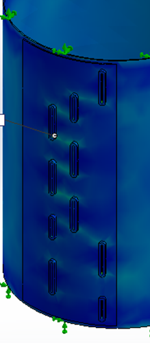
Sight glass arrangement as you see in the picture below.
Capture_uyqral.png

Capture2_plaf4i.png


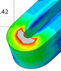
But FEA result showed that at sharp edge of round corner of sight glass base frame has stress around 600-700MPa and deformation occured around 2.5mm
Capture3_rjqpyw.png


Can I still fabricate this vessel from this design?

Or I cannot use this sight glass model from this vendor?

Please kindly suggest. I never designed this kind of sight glass before. How can I make sure to my customer that the design is safe.

Thank you very much.
 
Replies continue below

Recommended for you

Is their sight glass designed to be used in the vertical orientation? Can the manufacturer supply calculations or proof test results showing their design is able to withstand 10 bar?
 
What you see is a peak stress that's not necessarily relevant to the analysis (depends on fatigue requirements). The displacement of 2.5 mm, however, sounds odd and should be checked.
You should first of all check the opening reinforcement. For a single elongated opening you use the maximum opening width as the diameter of a circular opening. This is relevant to your assessment per VIII Div.1.
For non isolated openings also a simple analysis should allow to check compliance to code.
Anyway, the supplier of the sight glasses should (depending on the scope of supply) be able to provide all the necessary justifications and documentation.

prex
[URL unfurl="true"]http://www.xcalcs.com[/url] : Online engineering calculations
[URL unfurl="true"]http://www.megamag.it[/url] : Magnetic brakes and launchers for fun rides
[URL unfurl="true"]http://www.levitans.com[/url] : Air bearing pads
 
fegenbush

My case is I never ordered from them. I just compared the catalog and selected the model that i think it fits to my vessel for machining it follow the sizing that specified in their catalog by my vessel fabricator.

But as far as i compared, Most sight glass vendors use base frame around 25-35mm for withstanding 10 bar.

prex

That's interesting! It's not difficult to prove opening reinforcement by calculation to my customer

But I have no idea how to explain that we can ignore Peak Stress since I'm not specialist in this field.
 
And I also increase thickness from the catalog.

What does this mean? What did you change?
 
Racookpe1978,

If the model in the catalog specify thickness 35mm

I model using thickness 50mm instead
 
Sight glasses like the ones you show do not require that you cut slots in the tank for the entire length of the gage. All you need is a hole (~1/2") drilled through the tank wall at the top and the bottom of the gage. If you do that then you also do not need a doubler plate.
 
Compositepro,

Customer said their fluid can easily solidified.

That's why we have to design like this.
 
Is the pitch between the vertical rows in the first picture too small? Looking at the two slots on the right column (very top and very bottom) and stresses seem lower.
 

31nuac said:
If the model in the catalog specify thickness 35mm

I model using thickness 50mm instead

But what part of the sightglass was the 35 mm, and where is the 50 mm going to come from if you order their sightglasses?

Where is the 50 mm distance?
 
Size h[sub]1[/sub] is 25 mm in the catalog, not 35. And I don't see any advantage in raising it to 50 mm, all the added material is likely out of the reinforcement limits.
Concerning the peak stress, you don't need to show that calculation to your client, you even didn't need to perform that calculation to certify conformance to ASME VIII rules.
See also:
UG-23(c) said:
It is recognized that high localized discontinuity stresses may exist in vessels designed and fabricated in accordance with these rules. Insofar as practical, design rules for details have been written to limit such stresses to a safe level consistent with experience.
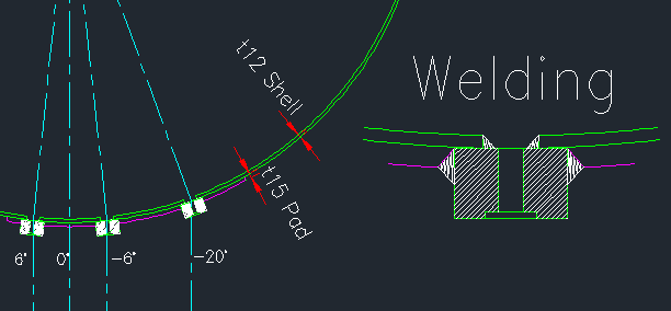
In your model I don't see the vessel wall and the reinf.pad: can you better describe your model and the results?
If you are not specialist in vessel design, then you'll go deeper in uncertainties by performing calculations that you cannot interpret: you should refer to an expert in the field.

prex
[URL unfurl="true"]http://www.xcalcs.com[/url] : Online engineering calculations
[URL unfurl="true"]http://www.megamag.it[/url] : Magnetic brakes and launchers for fun rides
[URL unfurl="true"]http://www.levitans.com[/url] : Air bearing pads
 
prex said:
In your model I don't see the vessel wall and the reinf.pad: can you better describe your model and the results?
If you are not specialist in vessel design, then you'll go deeper in uncertainties by performing calculations that you cannot interpret: you should refer to an expert in the field.

Yes, the numbers, the over-stress indicated by the FEA model, the FEA model and its assumptions, plus the changes the OP has mentioned don't look right. The OP needs to get an outside independent review of this idea before the dwg is approved. Most certainly before installation and welding begins.

First step is to get the sightglass fabricator to approve the 25 -> 35 -> 50 mm "change".
 
This looks like an excellent Radar Application.

Regards
StoneCold
 
Prex,

May I have your email address? I will send all detail and story why i'm now struggling on this analysis.
 
We are required to not publicly exchange our emails on this site.
Also, you can get real help here, but only if you are already knowledgeable on the matter to clearly explain your problem. Otherwise you really need an expert (and not a virtual one!)

prex
[URL unfurl="true"]http://www.xcalcs.com[/url] : Online engineering calculations
[URL unfurl="true"]http://www.megamag.it[/url] : Magnetic brakes and launchers for fun rides
[URL unfurl="true"]http://www.levitans.com[/url] : Air bearing pads
 
I'm not allowed to publicity post full detail drawing.

I'm now seeking for the experts also.

But I'll try to explain what I've done so far...

1. A vessel as mentioned in topic was already made but with different sight glass design and NO reinforcing pad for sight glass opening. (There is a story behind why this vessel was approved to made with no reinforcing pad and I dont want to explain this stupid mistake)

2. A vessel in (1.) already failed hydrostatic test @3bar(of test pressure 7.8bar) Sight glass base frame started to deform that can easily see and cause water leakage. The test immediately stopped.

3. After rechecked we found that we made mistake. Reinforcements are required as UG-36 said "When the long dimension of an
elliptical or obround opening exceeds twice the short dimensions, the reinforcement across the short dimensions shall be increased as necessary to provide against excessive distortion due to twisting moment." That's why we decided to go for FEA.

And the sight glass that we design were too long compared to sight glass catalog from many vendors.(There is also a story behind why we designed sight glass this long)

4. We tried to perform FEA with the vessel that already failed test and found the deformation occurred around 10mm @7.8bar at middle plane of sight glass frame outward vessel shell. And peak stress also occurred over 1000MPa at the same area shown in topic.

5. We redesigned sight glass frame to be shorter and thicker and added reinforcing pad and performed FEA again. Now the deformation at the same area as (4.) has been reduced to under 2.5mm. And peak stress reduced 600-700MPa.

6. Now we have no idea if the peak stress like this could cause failure or not. Everyone who is involved never experienced this situation also. Nobody can confirm or give a better advice.

So I'm hopeless now.


Your leakage is related to deformation and not stress. And peak stresses are only relevant in terms of fatigue. Find me here...
 
So it seems you've come across the grounds of this (in)famous statement of ASME VIII. It has been the object of a few discussions here on eng-tips, but no clear answers were ever provided.
These are a few considerations of mine, in trying to help:
- in the first version of the vessel you had no sufficient reinforcement per UG.37 for the openings; with the addition of the reinforcement pad you should now be OK
- the problem during the test was not due to this lack of reinforcement, because the test was stopped at a lower pressure
- the problem was due exactly to the phenomenon that the (in)famous statement addresses: excessive distortion due to what they inapprpriately call a twisting moment. I figure it out as the straight border of the opening bending outwards.
- if the opening reinforcement per UG-37 is correct, an excessive distortion cannot cause failure for a single application of the load, but may of course cause leakage, or possibly brake the glass
- the high stresses in the curve of the rim (or frame) are due to this distortion; these might be better classified as secondary stresses, instead of peak stresses; you should try to halve them, with respect to the 700 MPa value, to be in a safe condition
- certainly increasing the wall (or pad) thickness helps much in reducing the distortion; I'm not sure whether increasing the length (25 to 35 to 50) of the rim is also useful, you could rerun the model by changing this parameter only
- I think that you should further increase the pad thickness (possibly incorporating the opening frames into it), till you get the stresses in the curve down to some 350 MPa and till you get a deformation that you can judge compatible with leak tightness.
If you want a rigorous way of determining that stress limit, you should perform an analysis per Div.2 of ASME VIII, but it is a very complex topic, if you've never done such an analysis.


prex
[URL unfurl="true"]http://www.xcalcs.com[/url] : Online engineering calculations
[URL unfurl="true"]http://www.megamag.it[/url] : Magnetic brakes and launchers for fun rides
[URL unfurl="true"]http://www.levitans.com[/url] : Air bearing pads
 
Thank you very much prex and everyone.

I'm really appreciated your help.
 
Status
Not open for further replies.

Part and Inventory Search

Sponsor