Eng-Tips is the largest engineering community on the Internet

Intelligent Work Forums for Engineering Professionals

Importance of dial indicator position while measuring 3

Status
Not open for further replies.

elinah34

Mechanical
Aug 19, 2014
115
0
0
IL
Hello everyone,
I watched the milling machine worker measuring the upper surface of the machined part while it was still on the milling machine.
He didn’t really pay attention to the dial indicator posture/position relative to the part and/or machine.
I wonder if there is no importance to the dial indicator posture/position.
NEW_1_iah46w.jpg

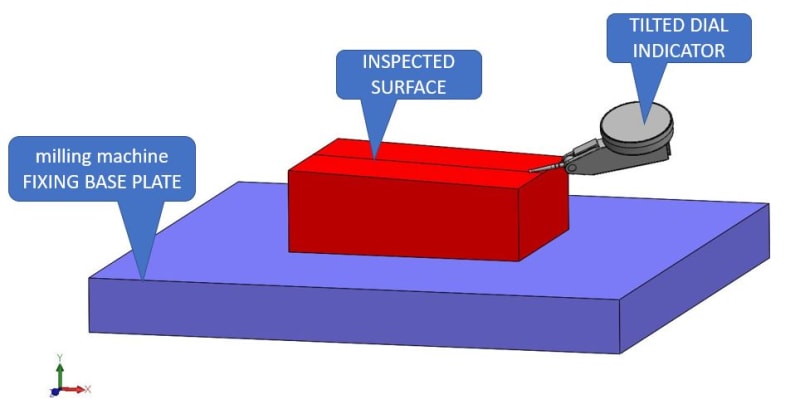
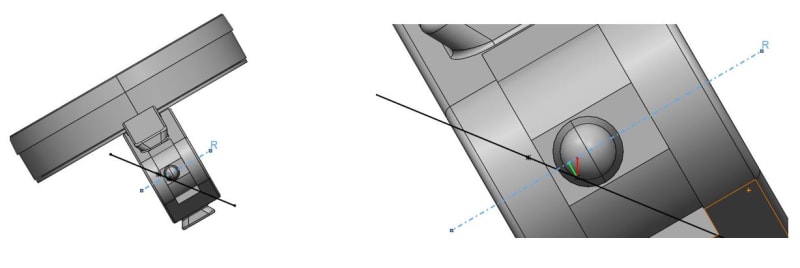
I think that he should theoretically want to make the dial indicator “R” axis of rotation so he will be parallel to the milling machine FIXING BASE PLATE.
NEW_2_clqkdu.jpg

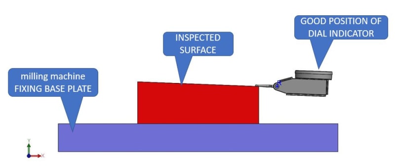
Any other position could lead to a projection of the real surface deviation.
What do you think?
NEW_3_jxzuxa.jpg
 
Replies continue below

Recommended for you

This is called sine error. For reasonably small tilt angles the effect is small.

For example, if the tilt is zero and the indicator movement is at 90 degrees to the surface. The sine of 90 degrees is 1.00~, so the actual deviation is divided by 1.00~ to get the indicator value

If the tilt is 90 and the indicator movement is at 0 degrees to the surface. The sine of 0 degrees is 0, so the actual deviation is divided by 0, which is clearly useless.

For more reasonable amounts of tilt, like 5 degrees, then the angle of interest is 85 degrees and the sine of 85 is .9962, so any reading will be too large by that multiplier. A real value of 0.005 will actually indicate as 0.005/.9962 = 0.00502 which is a difference of 0.00002

At 45 degrees as it becomes noticeably large a result by a factor of 1/0.707 or 1.414

Sometimes it doesn't matter. For example, if the use is to level a part in a vise on a mill, then 0 on the dial indicator is still zero and the tap of a brass hammer on the part isn't calibrated to the exact deviation. The error could be 2:1, but 2*0 is still 0.

if you are looking to inspect a range, then getting with 5-10 degrees is best, within 1 degree will be an undetectable for most uses.
 
Elinah34
Check out the link to the mitutoyo pdf file.
Depending on the manufacture the design their dial indicators to be used with a slight angle.
Normally when a dial indicator is purchased
, there is an manual with it. Which explains proper procedure.
10 degrees, the length of the tip is inter changeable. Which will affect accuracy.
But can easily be calibrated to gage blocks.

 
Once we unknowingly started using a "centering" or "coaxial" indicator for some linear feature checking. Flatness or parallelism or something.

Little did we know the readout was half ( or maybe twice?) the actual motion of the indicator tip.

After a few unexpected results, checks with a .015" feeler gage slid under the indictor tip made it clear what was going on.

I think a similar test would quickly help identify if the orientation of the indicator is affecting the measurements reported by the indicator.
 
That's hilarious. Next up, sneak a pattern-maker's rule into an newbie's hands and see how long it takes to figure out the measurements are scaled up to account for shrinkage.
 
There can be many errors with those type of indicators, and is why they are best to just represent a zero point and not an indicated range.
Use a height gauge or machine dials or digital read out to read the true error or dimension.
 
Status
Not open for further replies.
Back
Top