Continue to Site

Eng-Tips is the largest engineering community on the Internet

Intelligent Work Forums for Engineering Professionals

  • Congratulations waross on being selected by the Eng-Tips community for having the most helpful posts in the forums last week. Way to Go!

Imported STEP to Solid body 2

Status
Not open for further replies.

mehmoka

Mechanical
Nov 12, 2018
6
Hi,
A imported a step file and i want to export it as stl to print it out with a 3D printer. When i import the step file i get faces too, a tried to use saw to make from them solid bodys but it didnt work.
Do you have any idea how can i do this job?
 
Replies continue below

Recommended for you

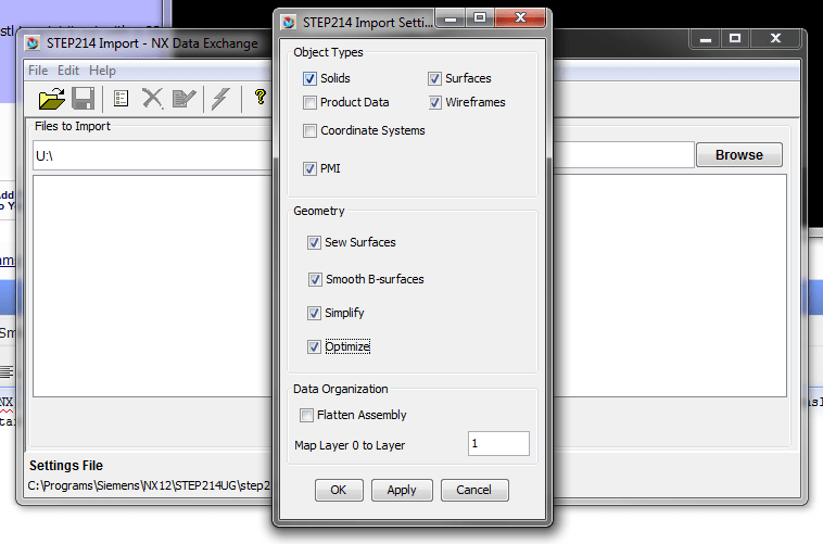
Instead of importing it directly into NX, use the external translator. It will give you more options in the setup which it will apply during translation.
You can find the translators in your start menu. The translator will create for you a partfile which you can import.


step_qkkcju.png


Ronald van den Broek
Senior Application Engineer
Winterthur Gas & Diesel Ltd
NX9 / TC10.1.2

Building new PLM environment from Scratch using NX12 / TC11
 
I would suggest you use Examine Geometry to find and repair the gaps. If you know the STEP file was a solid in the source CAD software, repairing the gap(s) might be a bit more challenging. If the STEP file was only a surface model in the source CAD file, turn off Automatic Sew on the import dialog as that's not helping you any. For the surface model, find & repair the gaps that will not sew. Gaps are more than likely the root of the issue unless the source model was garbage from the start.

Tim Flater
NX Designer
NX 11.0.1.11 MP8
GM GPDL 11-A.3.4.2
Win7 Enterprise x64 SP1
Intel Core i7 2.5GHz 16GB RAM
4GB NVIDIA Quadro K3100M
 
Thanks Xwheelguy,
You have probably right, there are lots of gaps in the model and manually it takes lot of time. Is there any automatic function in NX to fill the gaps?
 
mehmoka,

You can try doing a Heal Geometry which ultimately exports the current part to a new part but I'm not sure if that will correct larger gaps. Typically I resort to untrimming and retrimming (or some form of extending the surfaces beyond the gaps and retrimming - up to you), if possible. I'm wary of using things like N-sided surface and Fill type commands, as that can result in topology changes. It's all dependent on each model and in how bad of shape it might be. Without seeing the actual model, I'd just be guessing and that's not going to be of much use to you.

Tim Flater
NX Designer
NX 11.0.1.11 MP8
GM GPDL 11-A.3.4.2
Win7 Enterprise x64 SP1
Intel Core i7 2.5GHz 16GB RAM
4GB NVIDIA Quadro K3100M
 
I had a look, this is a really strange model.
The stepfile is exported by Solidworks, but it contains many objects that NX / Parasolids doesn't like.
My guess is that some of the geometry in this model is created in Solidworks and some is created in some other system, maybe a surface modeling system and then imported into Solidworks.
( Solid works does not create that type of ugly blends.) Roughly 50/50 solids and Sheet bodies.

What is your requirement on this model ?
The intended usage ?
Can you stay with the mix of Sheets and Solids ?

Regards,
Tomas

 
I just want to print it out with a 3d printer but the softver of the printer cant slice it because of the gaps and unclosed curves.
How do you know that partly it is made with Solidworks?
 
The step file is written by Solidworks. - You can open it with a text editor , all( professional-) programs write the exporter name in the start of the file.
Solid works (Still ?) uses Parasolid, so do NX and several other systems.
Parasolid is the "geometrical engine" in these systems , and the exact specifications of each little piece of the surface /face/ solid etc is "the same" in most of these.
- When you get data from a system that uses Parasolid , it is normally both "clean" and works as expected.
The pieces that are solids, such as the foundation in your file is both clean and "normal" , my guess is therefore that it was created in SW.
The intermediate arm, is a sheet body, the faces have several "unexpected" edges. ( Unexpected from my experience of how NX / Parasolids does things ), i would doubt that that was created in Parasolids ( i.e Solidworks), rather some "industrial design system" surface modeler. ( Rhino ?, Alias ?)

Regards,
Tomas

 
Status
Not open for further replies.

Part and Inventory Search

Sponsor