Continue to Site

Eng-Tips is the largest engineering community on the Internet

Intelligent Work Forums for Engineering Professionals

  • Congratulations cowski on being selected by the Eng-Tips community for having the most helpful posts in the forums last week. Way to Go!

In practice how do people consider EC2 parabolic stress block 1

Status
Not open for further replies.

Agent666

Structural
Jul 2, 2008
3,080
Hi All

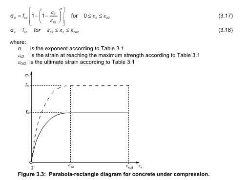
Couple of questions about how people deal with the EC2 parabolic-rectangular (or any other non rectangular) compression block in practice/practical design, especially when dealing with non-rectangular sections or bi-axial bending where the width of the block is changing with respect to depth from the extreme compression fibre:-
Untitled_d0zjl2.png


For a rectangular section (i.e. beam) with flexure about one axes only, its quite easy to resolve the parabolic distribution to an equivalent rectangular stress block for the purposes of calculating the ultimate capacity of a section, i.e. same area and centroid via integrating appropriately the 3.17 equation in EC2.

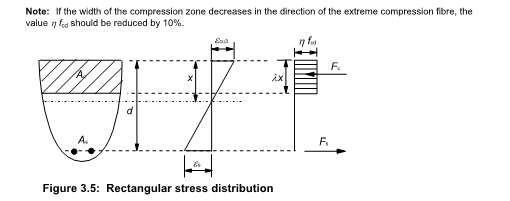
This only works for rectangular sections with one principle axes moment. For anything non rectangular (say a circular section), or bi-axial bending in a rectangular section (i.e. column), do people typically just use the rectangular stress block from EC2 and apply the 10% reduction to η (the reduction in f_ck) noted in clause 3.1.7(3) and not 'go there' with the parabolic curve as it all gets too hard.
Untitled_smqj91.png


If doing things by hand I'd simply do it this way as its close enough for ultimate capacity, but for spreadsheets you can obviously go to the effort of working things out using the parabolic or bi-linear relationship and apply the EC2 parabolic distribution to the non-rectangular section and work out the area and centroid (presumably need to integrate the 3.17 relationship over the curve and the section shape (i.e. find the volume and centroid of the resulting 3D stress block in the section).

I can't imagine this is too hard, though my integrating skills were put to the test just doing the 2D problem for a rectangular section, and have never attempted finding the centroid and volume of a 3D shape like this!

So how do people deal with this in practice, we are told these more advanced curves are better/more accurate, etc, etc... but is it all just too hard to do in practical design unless you are using some software that already does these things for you?

Also is anyone aware of any generalised solutions for the volume and centroid of the parabolic-rectangular stress block for 1) circular or 2) rectangular sections with biaxial actions?
 
Replies continue below

Recommended for you

OK, so part of my thesis when I was getting my masters was on this. I don't have time to digitize the thesis right now but I can tell you one thing. Using a parabolic stress strain curve for concrete instead of the rectangular approximate stress block will yield more accurate results. But in general we are only talking about less than a 1% improvement in terms of gaining strength or accuracy.

Also for my thesis I was using the following program which can analyze columns or beams for biaxial bending using rectangular or circular sections. The program will yield a three dimensional failure envelope. The best part is that it is free. Please keep in mind I use this primarily for short columns or beams. It does not account for slenderness effects of slender columns.


It requires mathCad 15 to run and the program you want is called "Biaxial Column v3.0".

Because this is mathCad you can go through the equations and replace the rectangular stress block with a parabolic one if you desire. But again unless you are doing this for research purposes it is a waist of time as you will only extract a very small fraction of benefit by doing this. The rectangular stress-block simplification actually is pretty accurate. In my thesis paper I compared the results of several concrete beam testings and compared several different parabolic stress strain curves. I found the best one but honestly it isn't a big deal which one you use for the most part.

Tomorrow I will try to get my paper uploaded so you can review it. It goes through the numerical process of how the program works and why it is so effective. It uses a really nice approach to solving the biaxial problem. It also allows you to essentially analyze odd shapes. You aren't limited to just squares, rectangles, and circles. You can do triangles for example if you want to.

John Southard, M.S., P.E.
 
I do not use (nor am familiar with) EuroCodes, but I did read a good paper by fellow E-T'er IDS entitled Time to Dump the Rectangular Stress Block? where Doug discusses EC2 in some detail with comparison to other codes: Link

His website has some great info too, with many automated spreadsheets, including ultimate strength under combined axial load and biaxial bending - not sure if it can handle curvilinear stress blocks, but worth a look: Link
 
Ingenuity,

You have been using it for 10 years in RAPT! We changed from a parabolic curve we developed to handle service stress curvature calculations many years ago to the Eurocode curve about 10 years ago as it predicts higher strength concrete effects very well.

You find some very interesting (and sometimes worrying) results using it.

Worst is for column biaxial results where the actual capacity is nothing like the design code Mx and My combination approximation would suggest.

 
Thanks for the comments Ingenuity.

At the moment my spreadsheets for non-rectangular sections and bi-axial bending only work with a rectangular stress block, but it's really not that hard to deal with parabolic. I'm in the process of updating them for the new AS 3600, so I'll look at adding parabolic stress blocks as well.

Doug Jenkins
Interactive Design Services
 
Southard, look forward to checking out the method in your thesis if you get a chance to scan & upload it. Unfortunately I don't have Mathcad to be able to use the bi-axial column program you mentioned.

IDS's paper was what got me thinking about this, specifically how people treated the application of these more advanced/accurate requirements in practice. Whether they really use the more realistic stress block (and how they implement it) or do they just apply the 10% fudge either based on using a equivalent rectangular stress block derived from the parabolic-rectangular one, or simply use the default Eurocode rectangular block as its close enough for strength like southard discussed.

rapt, for concrete I've always tried/had to work from first principles for bi-axial actions, using the rectangular stress block because its obviously pretty simple. In NZS3101 there is no simplified method like (Mx*/phiMny)^n + (My*/phiMny)^n like in some other codes.

IDS, I'm interested in how you would consider implementing the block, i.e. divide into strips of some finite width/depth and find volume and centroid numerically (adjust the depth increment until some reasonable degree of accuracy is achieved vs computation time), or some other way?

Any other comments from people using EC2 day in day out would be appreciated.
 
Agent66

Unfortunately rectangular stress block is useless for any thing but rectangular sections. But presumably NZS says the same as all other codes. A more accurate representation of the concrete stress/strain relationship can be used.

That is why we use the Eurocode model in RAPT.

If you look at a square symmetrical column at a biaxial angle of 45 degrees, the extreme fibre in compression has a width of zero, increasing to a maximum at mid depth.

A proper parabolic stress strain curve will put the maximum stress at that zero width and reducing stresses at increasing width with depth.

A rectangular stress block is based on an assumption of constant width so the "average" stress it uses assumes the width at the maximum compression is the same as at minimum compression.

Eurocode has a "rectangular stress block" approximation but it reduces the compression by 10% if the concrete width reduces towards the compression face. I doubt that even this is sufficient.
 
rapt said:
Unfortunately rectangular stress block is useless for any thing but rectangular sections. But presumably NZS says the same as all other codes. A more accurate representation of the concrete stress/strain relationship can be used.

Yeah it certainly does. But it only has a rectangular stress block that is similar, but not quite the same as the ACI one actually covered in the code, and no further guidance on anything else or any mention of the lack of accuracy at higher concrete strengths using the rectangular one.

rapt said:
A proper parabolic stress strain curve will put the maximum stress at that zero width and reducing stresses at increasing width with depth.
You are talking about the actual stress/strain relationship (figure 3.2 in EC2) applied using the parabolic-rectangular stress block (figure 3.3) not just the use of the parabolic-rectangular stress block on its own with a 'linear' concrete stress/strain relationship, right?

 
In practice I've always used the rectangular stress block to calculate MRd for simple rectangular sections - or rather used a single equation someone else derived to work out z. I don't doubt some clever chap has found some limitations for the rectangular stress block compared to the parabolic approach, but many RC elements have been designed using it over the years. It is a tried and tested method.

For anything more complicated I use a program called Oasys Adsec which I believe uses the strain compatibility approach to work out stresses/strains in the reinforcement and concrete based on the parabolic stress block. I think Autodesk Bridge is also popular for this, formerly known as SAM.

Its tried and tested over many projects, and as a busy designer I generally rely on what it tells me save for a quick glance over that it looks about right and checking that I've provided enough compression reinforcement etc.

Check out the Designers Guide to EN 1992-2 by Chris Hendy and Murphy which discussed in great detail background information about EN 1992. Its something I wouldnt mind knowing a bit more about, but unfortunately theres plenty else I want to read about.

gl
 
Agent666 said:
You are talking about the actual stress/strain relationship (figure 3.2 in EC2) applied using the parabolic-rectangular stress block (figure 3.3) not just the use of the parabolic-rectangular stress block on its own with a 'linear' concrete stress/strain relationship, right?

Figure 3.2 and 3.3 are two separate things. 3.2 is for structural analysis where actual stresses and deformations under large strain are important. 3.3 is a simplification for standard ULS design purposes. You can't get a parabolic-rectangular stress block if you assume linear stress/strain relationship.

I don't know what rapt uses, but in my opinion 3.3 is the appropriate one for ULS design.

Regarding the ACI stress block, it uses a fixed depth factor, which is highly unconservative for high strength concrete, compared with EC2 (and AS 3600), which have significantly shallower blocks at high strength, due to the reduced plateau width in the stress-strain curve.


Doug Jenkins
Interactive Design Services
 
Yeah my understanding was 3.2 is more for overall behaviour where material properties might vary along a member for a non-linear analysis. But across the member depth plane sections remain plane and all that.

I perhaps wasn't really initially following the following statement on a conceptual level trying to wrap my head around it, perhaps misinterpreting it:-
rapt said:
A proper parabolic stress strain curve will put the maximum stress at that zero width and reducing stresses at increasing width with depth.

A rectangular stress block is based on an assumption of constant width so the "average" stress it uses assumes the width at the maximum compression is the same as at minimum compression.

But let me explain what rapt noted in my own words for clarity:-
My understanding was that taking the 45 degree attack on a square column example, the area in compression is triangular. Because the depth/stress ratios for a rectangular block were derived from some 'arbitrary parabolic block' applied to a constant width section, they cannot be applied to the triangular volume of 'stress' as the centroid (i.e. depth factor) is not equivalent, in effect for it to be correctly applied, there would also have to be a width fudge factor applied for the compression area being triangular vs rectangular.

Considering the parabolic block from first principles takes account of the correct centroid considering the triangular area in compression and stress dropping off to neutral axis at some point, as the stress block distribution on the triangular area is intended to better represent the fundamental distribution of stress that is occurring, therefore its ultimately more correct to consider this approach for bi-axial actions?


rapt said:
A proper parabolic stress strain curve will put the maximum stress at that zero width and reducing stresses at increasing width with depth.
Given the parabolic-rectangular distribution, isn't the maximum stress constant to the depth from the corner to where the strain is equivalent to epsilon_c2, and it starts dropping off from this point?
This is the bit that is confusing me if taking what rapt noted at face value. Stress does not drop off immediately from the corner based on the parabolic-rectangular relationship in EC2, its constant for some finite distance based on the EC stress block for analysis purposes? Rapt, were you talking more about true behaviour in real sections, or am I missing something fundamental thats going on?


Effectively based on the shape of any arbitrary shape of compression area, equivalent rectangular block parameters could be derived from the parabolic-rectangular relationship (3.3), and these would only valid for that geometry of the compression area.


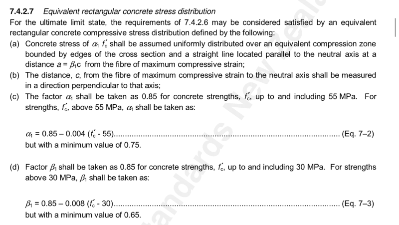
FYI NZS3101 also adjusts the depth factor, thats the difference from ACI at higher concrete strengths, it varies according to the following beta_1 relationship (might want to consider throwing it into your RC spreadsheets as another option). Its meant to overcome some of the limitations of the ACI approach:-
Untitled_tyfedn.png
 
Agent666 - for a parabolic-linear stress block (such as EC Fig 3.3) what you say is correct. Nonetheless, the area with the peak stress will be much less than for a rectangular cross section, so the calculated depth of neutral axis will be too small, which was rapt's point. This remains true whether you use a pure parabolic stress-strain curve, or a parabolic linear.

Regarding the NZ code effective depth provisions, I should have known that. The provisions are actually very similar to AS 3600, but not quite the same (and we have just changed again).

I agree I really should add the NZ code to my spreadsheets (along with updated AS 3600 and 5100, and adding parabolic-linear stress strain to the non-rectangular and bi-axial functions).

Incidentally, the rectangular functions have an option to calculate the rectangular stress block factors that will give exactly the same NA depth as the EC2 parabolic-rectangular curve. It's quite a simple calculation, but for some reason none of the international codes that I know of give the same results (including EC2).

Doug Jenkins
Interactive Design Services
 
Agent66,

You are basically integrating F(width) * F(stress/strain) over the compression depth. To develop the rectangular stress block, width was assumed constant so they only integrated F(stress/strain).

With a width over the depth decreasing towards the compression face the higher stresses are being multiplied by the smaller widths thus
- reducing the total compression force for a specific neutral axis depth and
- increase the depth to the centroid of that compression force.
Thus for a rectangular stress block
- the neutral axis depth is under-estimated,
- the available compression force is over estimated and
- the available lever arm between C and T is over estimated.

So circular sections and any section where width reduces towards the compression face, which is most bi-axial calculations, the M and N estimated are over-estimated and neutral axis depth is under-estimated.

The reverse is true for sections where the width increases towards the compression face.

The other thing with concrete stress strain curves is the assumption that maximum strain is .003 and peak stress occurs at about .002 to .0022 strain. If you look at the Eurocode curves,

at low concrete strengths those figures are .0035 and about .0022

as concrete strength increases the maximum strain reduces and the peak stress point increases until about 80MPa concrete where they are both .0028. So there is no longer a constant stress region at concrete strengths above this and the stress strain diagram is nearly triangular. This is consistent with recorded concrete stress/strain diagrams.
 
I know RISA uses the parabolic curve for uniaxial bending. But, then uses the "simplified" uniaxial solution in the EuroCode rather than performing a complete biaxial condition.

This is a little odd because RISA has a parabolic curve option (using the method given in the PCA Notes) for the ACI code that works nicely for biaxial columns. I wouldn't think it would be too difficult to program a slightly different parabolic curve into the program for the EuroCode.

That being said, I remember testing the ACI biaxial columns (round and rectangular) and it made very little difference in the column results. Like Southard2 said... something along the lines of 1%.
 
Thanks IDS & rapt for the responses, nice and concise explanations!

Seems obvious in hindsight that the rectangular block won't adequately address the bi-axial case. But until now I'd never even considered or appreciated this because its just the way things have always been done.

Now if a code actually mentioned these potential limitations on the methods when discussing the limitations/applicability of the rectangular stress block, no doubt I'd have probably put some thought into it well before this point. Most of the discussion in code commentaries seems to be around addressing higher strength concrete behaviour as opposed to cross section behaviour when discussing the rectangular stress block approaches.

One other related question if I may:-

NZS3101 is based on/states a maximum compression strain of 0.003 for ULS design. EC2 is based on 0.0035 max for lower strength concretes and varying for higher strengths (as per your reply rapt).

Is it usual if adopting the EC2 curve to also adopt the higher/varying strain limit (I'm unsure what the limiting strain in AS3600 is for comparison). I'm wondering if its required to be consistent with the NZS3101 approach that you might need to scale down the EC2 limiting compression strains by a factor of 0.003/0.0035. Or if due to the more accurate approach its accepted practice to apply the EC2 limiting strain directly? Any thoughts on this, I'm just envisaging queries from reviewers relating to something that is perhaps outside of the hard limit on maximum strain in the code?

In part the limiting strains might for example historically be based on local mix designs, European concrete aggregates for example might be completely different to NZ and AU aggregates. I suspect its more to do with the fudge from true behaviour into the rectangular block though.
 
Eurocode also has a rectangular stress block, and it uses a .9 factor for this for cases where the width reduces towards the compression face. This has also been added to the latest AS3600-2018.

AS3600 requires a strain limit of .003 if the rectangular stress block is used.

It also allows the use of more accurate models. In that case in RAPT we use the complete Eurocode model with the varying maximum strain for AS3600 design as well as for the old BS8110.

Except for ACI which does not qualify to use of the .003 limit so we use the .003limit for ACI.
 
To answer the original question, I use numerical integration (100 slices of cross-section) in a spreadsheet to handle the parabolic-linear (P-L) curve when necessary.

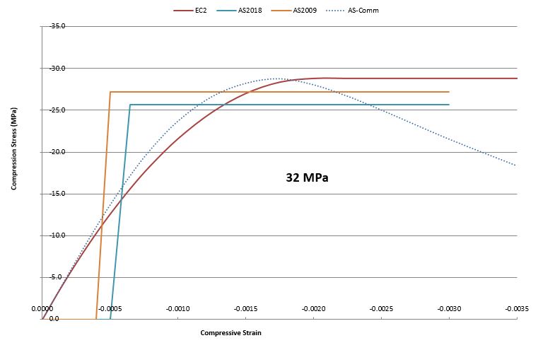
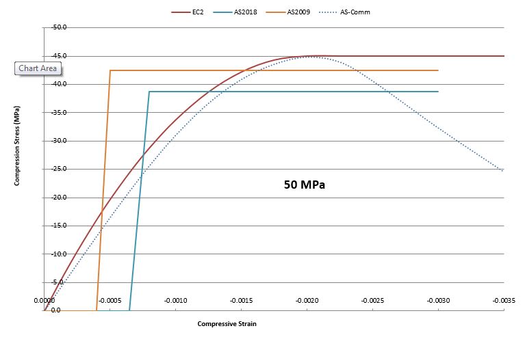
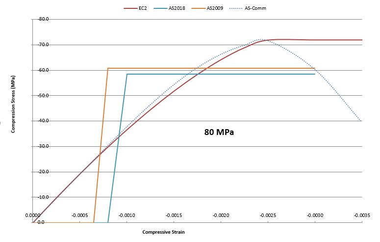
What is the effect of ignoring the post-peak stress drop when using the P-L relationship? By eye, the AS3600-2018 rectangular blocks look conservative whereas EC2 P-L look unconservative by comparison, though I haven't applied these to cross-sections to check.

Obviously need to specify which rectangular parameters are being used when comparing outcomes as they can vary widely as shown in the images. It doesn't look as though the 10% reduction for narrowing cross-section needs to be applied to 50MPa concrete for example (AS3600-2018; again unchecked).

I don't think it has been mentioned in this thread that the rectangular stress block has a lower peak stress (in AS3600 at least) and a fair chunk of the cross-section has zero stress. These combine to have the P-L stress greater than the rectangular stress over large parts of the cross-section (AS3600-2018). Less so in the past though as can be seen. Rapt, was this your doing?

Should just use triangular distribution for ultra-simplified analysis of high-strength cross-sections. Or no simplification: if you're not capable of a moderately complex calculation, stay in your lane and specify normal-strength concrete.

32MPa_jfyvph.jpg

50MPa_eup9jh.jpg

80MPa_ldhw2l.jpg
 
Steveh49 - Interesting results, but I'm not sure you are really comparing like for like there. I'll discuss further when I've had a closer look.

Did your AS-Comm lines come from Cl. 3.1.4 of the Commentary, or somewhere else?

Doug Jenkins
Interactive Design Services
 
IDS,
Yes, clause C3.1.4 for the AS-Comm line.

Do you mean they're not like-for-like because they need to be 'scaled' so the peak design strain is in the same place on the cross section? (ie at the extreme compression fibre). A bit hard to explain what I mean, but say for 32 & 50MPa, 0.003 for rectangular should align with 0.0035 for P-L because they're both at the edge of the cross-section. And 0.003 vs 0.0026 for 80MPa.
 
Does someone mind posting a screenshot of the derivation of those two 2018 Australian curves? I wasn't able to download the draft when it was available, as for some reason they wanted to charge anyone outside of Australia for it. That commentary one looks pretty funky.

To compare apples with apples in terms of overall shape I have tended to make the curves non dimensional, plotting equivalent stress factor vs equivalent depth factor to see the fundamental difference in the curves. I think due to the differences in the neutral axis depth on real sections with the use of each curve, its actually pretty hard to compare anything but the capacity achieved and resulting reinforcement stresses.
 
Status
Not open for further replies.

Part and Inventory Search

Sponsor