Hi everyone, I'm looking at a situation I haven't encountered before and wanted to get some feedback if you have some time.
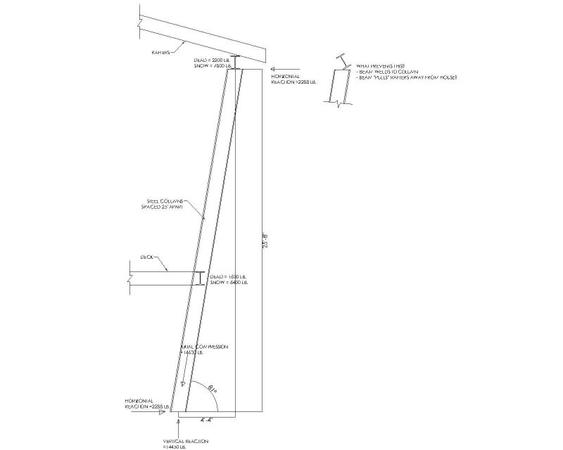
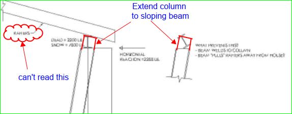
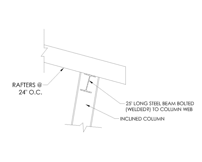
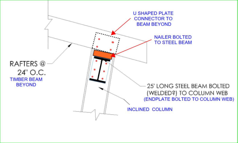
I've got a large custom home in a high snow load area with a covered deck at the back. The deck is 25' wide and has an inclined steel column at each end. There will be a beam at the top to carry the roof and a beam at the deck level. I have resolved the loads into axial compression in the column, vertical reaction at the bottom, and horizontal reaction at top and bottom using the D + .75S + .75L load combination. My question concerns the horizontal reaction at the top of the column. What prevents the beam from rotating as it tries to resist the horizontal force from the column?
The beam of course welds to the top of the column. It appears to me that the column tries to rotate the beam away from the house. The welds hold the beam in place, but then the beam tries to pull the rafters away from the house. Is this the correct load path? I need to make sure that the rafters are secured appropriately to the beam and back at the house so that the beam doesn't pull away from the rafters, and so that the rafters don't pull away from the house. That's how I see it, but wanted to see what you think. Do the deck joists see any of that force pulling them away from the house? Would appreciate any feedback. In summary:
1) The beam rotation is resisted by the welds from the beam to the column? I will also have web stiffeners.
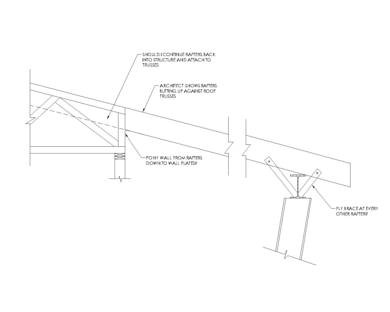
2) The beam imparts a horizontal force on the rafters pulling them away from the house?
3) Do the deck joists also pull away from the house?
4) Recommendations from your experience?
5) Is there a certain degree of incline where you need to design the column with a moment at the base instead of only vertical and horizontal reactions?
6) Where did I mess up?
Thanks!
I've got a large custom home in a high snow load area with a covered deck at the back. The deck is 25' wide and has an inclined steel column at each end. There will be a beam at the top to carry the roof and a beam at the deck level. I have resolved the loads into axial compression in the column, vertical reaction at the bottom, and horizontal reaction at top and bottom using the D + .75S + .75L load combination. My question concerns the horizontal reaction at the top of the column. What prevents the beam from rotating as it tries to resist the horizontal force from the column?
The beam of course welds to the top of the column. It appears to me that the column tries to rotate the beam away from the house. The welds hold the beam in place, but then the beam tries to pull the rafters away from the house. Is this the correct load path? I need to make sure that the rafters are secured appropriately to the beam and back at the house so that the beam doesn't pull away from the rafters, and so that the rafters don't pull away from the house. That's how I see it, but wanted to see what you think. Do the deck joists see any of that force pulling them away from the house? Would appreciate any feedback. In summary:
1) The beam rotation is resisted by the welds from the beam to the column? I will also have web stiffeners.
2) The beam imparts a horizontal force on the rafters pulling them away from the house?
3) Do the deck joists also pull away from the house?
4) Recommendations from your experience?
5) Is there a certain degree of incline where you need to design the column with a moment at the base instead of only vertical and horizontal reactions?
6) Where did I mess up?
Thanks!
![[pipe]](/data/assets/smilies/pipe.gif "[pipe] [pipe]")
![[upsidedown]](/data/assets/smilies/upsidedown.gif "[upsidedown] [upsidedown]")