Eng-Tips is the largest engineering community on the Internet

Intelligent Work Forums for Engineering Professionals

Inclined screws in wood under tension

Status
Not open for further replies.

PROFR

Structural
Feb 28, 2019
33
0
0
CA
I am trying to connect two LVL beams as shown below in which one of them will be under tension. I am using inclined lag screws. I checked the tension capacity of the screw embedded in member (b) considering the end grain condition and it is OK. I am not sure how to check the screw capacity in member (a). It there any check needed here?

Untitled_wgeblw.jpg
 
Replies continue below

Recommended for you

Yes, there's definitely something needed--either calcs or detailing. So far you checks only get the load from member (b) into the lag screw, so you need to get it from the screw to member (a). The two ways to do that are bearing at the head of the screw, or having screw threads engage member (a), or a combination of those two. This is complicated a bit since your screw head isn't bearing flush on member (a), and also typical lag screws have an unthreaded shaft at the head so you'll have limited threads engaged in member (a). For example, a 6" lag screw has a 2.5" unthreaded shaft, so if your LVL was 1.75" wide you wouldn't have any lag screw threads engaged with member (a).

If you can find lag screws that are fully threaded, or change to wood screws that are fully threaded, then that would simplify things. The member (a) check would just be thread withdrawl similar to your member (b) check.
If you can't get enough thread engaged with member (a), you can countersink the backside of member (a) at an angle to match the screw head. Then throw a washer on the lag screw and it's just a simple Fc perpendicular check for bearing against the side of member (a).

 
Thanks WeezerMike. I will be using bevel washers. If the bearing is not enough, i will switch to screws. Is there a difference in the withdrawal capacity between swan wood and Lvl if they both have the same G?
 
Hmm, interesting. The bevel washers are a little tricky because we aren't technically supposed to assume any friction between that washer and the side of the wood beam. So the lag screw bears on the bevel washer at an angle, and the LVL bears perpendicular to it's face, and then the washer tries to slide along the face of the beam. That's resisted by the lag screw acting as a shear dowel in the LVL. You can probably totally ignore that shear dowel effect unless you have weird conditions or edge distance concerns.

There's no difference between fastener capacities in sawn vs manufactured lumber. It's all based on G.
 
PROFR:
The NDS used to caution against using screws or nails, in tension, in end grain to carry real structural loads, and I suspect they still do. It is just not a very reliable means of transferring significant structural loads. At the same time, they do give some small allowable values for end grain loading of fasteners. I would have the builder drill a shallow, large flat bottomed, hole on the axis of the screws in member “a”, large enough for a proper washer under the head of the screw. Note that the bearing under the washer is neither perpendicular or parallel to the grain in member “a”. Look up the Hankinson Formula in your Timber Design textbook. Check with the LVL supplier for the allowable strength values of their products. I don’t think you should try to use a beveled washer at that kind of angle, and in this application. That’s just a stretch a bit to far, assuming you could buy one, at that angle.

What would happen if you installed the screw through member “b” and into member “a”? You would eliminate the end grain loading and have screw penetration into the side grain in member “a”, a much more acceptable application.
 
Dhengr, Thanks do much. The max tension is around 450 lb. There is reduction factor for end grain case, which is around 0.75. When you say screw b into a, do you mean like an end toe concept?
I can use a top gusset plate but I have a feeling that it might be overkill for this force. What do u think?
 
PROFR:
Read my last para. again, a little more carefully, I said “screw through member “b” and into member “a”. Meaning perpendicular to member “a” and back near the heel of member “b”, for max. end dist. on “b”, assumed you’d imagine that. What is an ‘end toe concept’? You certainly want to predrill for the screws and drill the shallow flat hole for a washer in member “b”. You might get buy with lighter predrilling if you use some of today’s structural screws, and only on member “b”. Use several for a little redundancy. Lag screws req’r. fairly large, multi-size drilling or they’ll tend to split the end of member “b”. Why didn’t you show the loads in your OP and the LVL sizes too. It would have made your question more meaningful and understandable. You would be surprised how important that info. is to an experienced engineer and his/her first impression of your problem, and some possible solutions. More engineering info. is better than almost none, but a nice sketch. Remember, we haven’t been looking at your problem for several hours, so when you come to anyone for help, give them enough meaningful info. so they can help, not just guess at what you need.
 
Like this, dhengr?

image_ypo792.png


Member 'b' cannot be in tension without some additional force, either from an applied force or another member meeting at the point of contact between 'a' and 'b'.

I tend to believe that gusset plates each side of the members are necessary. Using screws alone is not recommended.

BA
 
I said “screw through member “b” and into member “a”. Meaning perpendicular to member “a” and back near the heel of member “b”

I agree with BA that tension straps are more of a sure thing for this job.
 
BA:
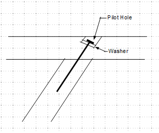
I wish I knew how to draw and manipulate sketches like you do, and that I had the software to do it. And, maybe, the patience to learn new tricks. I like Retired13’s ability to run his software to give use quick ‘order-of-magnitude’ force tabulations, shear and moment diags. and deflected shapes, etc. As long as we can agree on initial assumptions and loadings. Actually, I meant for my screw to be vert. in your sketch, and to go up through a predrilled hole in member “b” and penetrate into the side of member “a”, and near the heel on “b” as you show. Your detail is an improvement over the OP’ers. detail since it pretty much eliminates the screw tension loading in the end grain. But your detail will still show a significant amount of bolt bearing on the wood hole and shear and bending in the bolt, to transfer the tension load in member “b”, and separation at the joint. I like the idea of gusset plates t&b, but I get the impression he doesn’t want to see the bottom gusset pl., and I don’t like only one pl. to transfer the tension, don’t like the eccentricity of that loading.
 
dhengr,

I use RISA2D evaluation for free, there are limitations (no. of member, joints..), but the evaluation period seems never end. You can down load from their website. The learning curve is quite flat as long as you have some exposure to structural analysis software.

BA's graph is quite impressive. I don't what he's using now, but I use the OpenOffice Drawing Template, which was suggested by BA, it is quite easy to use, and free.
 
dhengr,

The old saying "a picture is worth 1000 words" is absolutely true. Some of the details we have to deal with on E-T are too complicated to describe using words alone, and engineers are not noted for their descriptive powers, so a decent graphics program is essential for clarity.

When randomname came up with thread507-471291 a few days ago, I started to re-examine some of the graphics packages mentioned. I have not had an opportunity to test them all, but currently, I like PDF Annotator and PDF X-change for pdf files. Bluebeam is probably much better for practicing engineers, but fairly pricey and not something I need at this time.

OpenOffice and LibreOffice are also good but are not specifically geared to pdf files and they are both free. I found they worked well until March 3, 2020 but then they both suddenly developed a problem with drawing polygons which I still have not been able to sort out. I can't say I'm working too hard on it though.

I have thought about learning to program graphics using Python, but so far have not advanced very far. The beauty of that is that you don't have to wonder why your software can't draw a particular shape. With Python, you can make it do whatever you want it to do.

BA
 
I totally agree with you that the best solution is using gusset plates. However, I have many of these connections with relatively low forces that ranges from 50 lb to 450 be lb. With 4 lag screws with head washers, I was able to get a capacity of 1350 lb, which is 3 times the maximum demand. The number includes the nds end grain effect. Although I like the gusset plate concept, I will have to use two of them at each connection top and bottom. I will probably add a face hanger. This might be regarded by the client as an overkill, which led me to think about trying to do it with only screws.
 
Any wood connection in tension depending on end grain threaded fasteners, as has been previously mentioned, is destined for the scrap heap and generally not recommended.

Do not use them.

Use a bent flange on both sides of the angled member, that is thru bolted and thru bolted to the supporting member.


Jim H
 
Status
Not open for further replies.
Back
Top