Continue to Site

Eng-Tips is the largest engineering community on the Internet

Intelligent Work Forums for Engineering Professionals

  • Congratulations SSS148 on being selected by the Eng-Tips community for having the most helpful posts in the forums last week. Way to Go!

Increase Column Capacity by Considering the Base Plate as Fixed 2

Status
Not open for further replies.

RFreund

Structural
Aug 14, 2010
1,885
This seems like a very simple question, but yet I'm not confident in my answer.

Let's assume you have an axially loaded steel column which you would normally design assuming a pinned connection top and bottom (K=1). Now you want to increase its capacity by considering the base plate to be fixed (and thus a smaller K value).
What moment would you apply to the base plate to verify it has the required strength and stiffness?
Would you now apply a moment to the column? If so what would that moment be?

Thanks in advance!


EIT
 
Replies continue below

Recommended for you

RFreund: I don't normally mess with columns for loading... one of the few areas that I tend to be conservative.

Dik
 
Agreed. You don't hear about steel beams failing much. It's always columns and connections. Beams flex and bounce well before catastrophic failure.
 
@ RFrend. I dont know which code and analysis method you are using. If you are using AISC Direct Analysis Method, K is always equal to 1.0. So fixing the column base might not reduce your k values. Yes, you need to consider p-delta, notional loads etc while designing column under direct analysis method
 
RFreund said:
What moment would you apply to the base plate to verify it has the required strength and stiffness?

I have to agree with Dik and Coty about being conservative with column end conditions assumptions... but, for the type work I have done, can easily imagine determining if an existing column can carry additional load.

This is how I see the problem. Do existing conditions allow Case "d" be treated as Case "b"?
Steel_Column-400_kapiza.png


This is what I would do:

1. Hypothetically "flip" the column on it's side and treat it as a cantilever beam with length equal to the true length of the column:

Column_Base_Evaluation-500_wksypg.png


2. Calculate the maximum allowable moment for the steel section that is the beam (the "flipped" column).

3. If the base plate and it's connections can withstand this moment, then the base is fixed (up to the column's limits). Assume K = 0.8

4. If base plate moment capacity is lower than Step 3, interpolate between K = 1.0 and K = 0.8

[idea]
[r2d2]
 
If there's any flexibility in the footing and soil below the footing then pure fixity isn't realized and you might be closer to k = 1.0 than you think.

Check out Eng-Tips Forum's Policies here:
faq731-376
 
If you're treating it as a fixed connection, there's probably a minimum connection capacity required by the code. You'd have to design for the greater of that or the moment from analysis.

The Australian standard has a limit on how fixed a footing can be taken as - maybe similar in other codes. Alternatively, model the column, footing and connection and run a buckling analysis might be an option.
 
For better or worse, this is something that I've done myself in the past. At that time, I gave the matter a good deal of careful consideration and came to the conclusion most "pinned connected" gravity columns can be considered fixed at the base for the purpose of buckling evaluation. Here's what I think I know:

- It's not a simple question so feel no shame.

- An axially loaded column effectively prestresses its base connection. As such, you've got amplified stiffness there until that prestress is overcome.

- You know how we do/did the 2% stuff for nodal bracing and the requirement usually seems almost laughably paltry? It's a similar situation here. The base fixity is just another form of bracing, forcing the column to buckle into a different, higher energy mode. And like the 2% nodal bracing, it really doesn't take much to get the job done. So while there absolutely are valid sources of rotational flexibility here, I would submit that it is unlikely that they would meaningfully compromise the fixity required.

- All bracing has both a strength and a stiffness requirement. That said, stiffness dominates this situation and I would not be loosing much sleep over the actual moment capacity of the connection. That, particularly given the prestress effect that I mentioned above.

- Recognize that all the moment capacity in the world at the base connection doesn't necessarily guarantee you enough stiffness there. See JoshPlum's exceptionally lucid discussion of this in the other base plate fixity thread active right now.

- If you're bound and determined to asses strength, I think that this would be a rational procedure:

1) Set up a quick non-linear model of your column with the base fixed. I like Mastan for this kind of stuff as it's free and fairly transparent/verifiable.

2) Apply your load in increments and build an initial imperfection into your model to get the ball rolling.

3) The column displacement should close in on a limiting value at which point statics under the deformed shape will give you a moment at the base.

4) Double the moment at the base. Or whatever multiple makes you feel warm and fuzzy. This will likely be a small number that's easy to deal with.

- Somewhere out there on the interweb, there is s thoughtful analysis looking at whether or not we can consider the bases of basement retaining walls to be fixed. And the conclusion is that, primarily for reasons of foundation flexibility, that is probably not practical. I believe that there are significant differences between that situation and this one however. And if somebody can locate the analysis, I'd be happy to attempt to speak to those differences.


I like to debate structural engineering theory -- a lot. If I challenge you on something, know that I'm doing so because I respect your opinion enough to either change it or adopt it.
 
Thanks for all the replies. Some followup questions/responses below:

@Dik & Coty: I can agree with this is most practical situations, but I am internally troubled that I can't confidently answer these questions in theory or based on codes.

@BAGW: I'd like to be able to answer the question based on principles of engineering and then figure out how to best apply any code. I know that a column with a fixed or semi fixed base has more axial capacity than one without. But how do we get there?

@Sliderule: Thanks for this. This is a pretty simple straight forward approach. Seems reasonalbe to me as well.

StevenH said:
Alternatively, model the column, footing and connection and run a buckling analysis might be an option
This is pretty generic statement, but I agree, this is the path I want to go down.

Kootk said:
It's not a simple question so feel no shame
I appreciate that. Interestingly enough I was in the middle of dusting off Mastran2, when I decided to refresh this page. I'm glad to see it seems I'm on the 'right' path.
Also I assume this is the thread with Josh's comment that you are referring to: LINK

Sidenote - Mastan2 has a pretty good learning module series for anyone interested.

I think Kootk has elaborated on what Stevenh suggested and what I've started to do.

Here's what I did, please comment as you see fit:
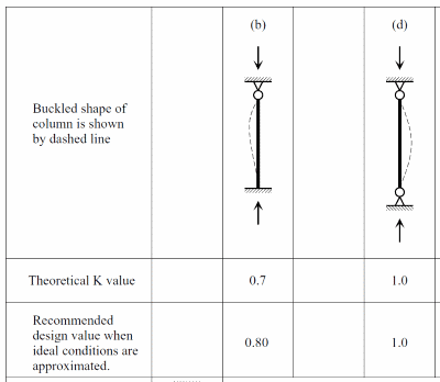
I set up a model consisting of a single column in Mastran2 with boundary conditions as follows : Restrained in X-direction at the top of the column, restrained in X,Y and Rot about Z at the bottom of the column (X-Y in the plane of the column and Z out of page). For those playing along at home:
Height: 16'
Column: HSS 8x8x1/2
Fy: 46 ksi
E: 29000ksi
I segmented the column in to 8 elements. So you have 9 nodes.
I Applied a 100kip load to the top of the column

I ran an Elastic Critical Load Analysis (aka Buckling analysis or Eigenvalue analysis) using planar frame for my analysis type. This gave me the deformed shape to start with, it is some sort of sin wave shape (slightly different because of the fixed base). My load ratio was 19.86, so the elastic critical buckling load was 1986 kips.

In Mastan2 you can use this deformed shape as a starting point to perform a 2nd order analysis. So I selected node 7 which is near the center of the column (node 1 is bottom and node 2 is at the top) and offset this node equal to H/1000 (i.e. 16'/1000 = 0.192"). Mastan2 will then offset the rest of the nodes proportionally to that your starting geometry is in the shape of the "sin wave".

I then ran a 2nd Order Inelastic analysis with the 100 kip load applied, same boundary conditions and the column geometry was "bent" in the "sin wave" I described above. Additionally I selected a "E" as E_AISC which I believe accounts for residual stresses in the column, I'm not sure what the program actually uses though and can't seem to find this. My load increment was 0.01 and Max number of increments was 10,000 for the record.
(Side question - I still want to know why they settled on the name "2nd Order")

This resulted in a load factor of 5.54 (i.e. 554 kips) and a moment at the base of 226.2 kip*in or 18.85 kip*ft. In the results tab you can change your load factor and check the moment reaction at the base. So if you reduce the load factor to your actual applied axial load you will get your moment demand on the base plate.

Side Note:
I then checked the same column as pin-pin and got a LF of 4.91 (i.e. 491 kip). The AISC manual lists the capacity of an 8x8x1/2 as 284kip, 426kip respectively. So there is about 3.5% difference there. I also re-ran all the calcs using a deflected shape from pin-pin and redefining the base fixity and got basically the same results.

Getting back to the results:
The critical loads are 554 kips and your moment demand is 18.85 kip*ft (note that you should check the moment isn't higher at any other node).
So for ASD your allowable buckling load would be 554/1.67 = 331.7 kip
And moment capacity would be:
M.c = Z.x x F.y => 37.5in^3 x 46ksi /1.67 = 1032.9 kip*in

So lets say that you axial load is 300kips (ASD), if I reduce my load factor in Mastan2 so that I'm effectively applying 300kip to the column I get a moment of about 60kip-in in the column.
Check unity:
300/331.7 + 60/1032.9 = 0.96 OK//

I'm a little unsure about this last part (the design check). Does this seem correct?

The other question I have is regarding the stiffness of the base plate. I'm still not sure what this needs to be, I'm looking through a few texts and will post back with some thoughts.

Thanks Again!

EIT
 
I am with JAE on this. What is the base plate connecting to. If there is any possibility it can rotate, then the the ability of the baseplate connection to transfer moment is meaningless.

And "prestress" does not stop rotation!
 
rapt said:
And "prestress" does not stop rotation!

Prestress / pre-csompression between connected parts deficient in tension capability increases rotational stiffness at the interface. You know, kinda like with prestressed concrete cross sections? Obviously it doesn't stiffen the dirt under the footing or anything magical like that. The PCI handbook has a method for estimating the rotational stiffness of conventional spread footingw that might have application here.

Actually, I take it back, precompression in the column probably does stiffen the dirt under footing. I just have no idea how to quantify that so I'd be inclined not to attempt it.

I like to debate structural engineering theory -- a lot. If I challenge you on something, know that I'm doing so because I respect your opinion enough to either change it or adopt it.
 
Status
Not open for further replies.

Part and Inventory Search

Sponsor