Hi all,
First time poster so please go easy on me. Because integrity reo is relatively new to Australian standards my supervisors are not a lot of help for me here.
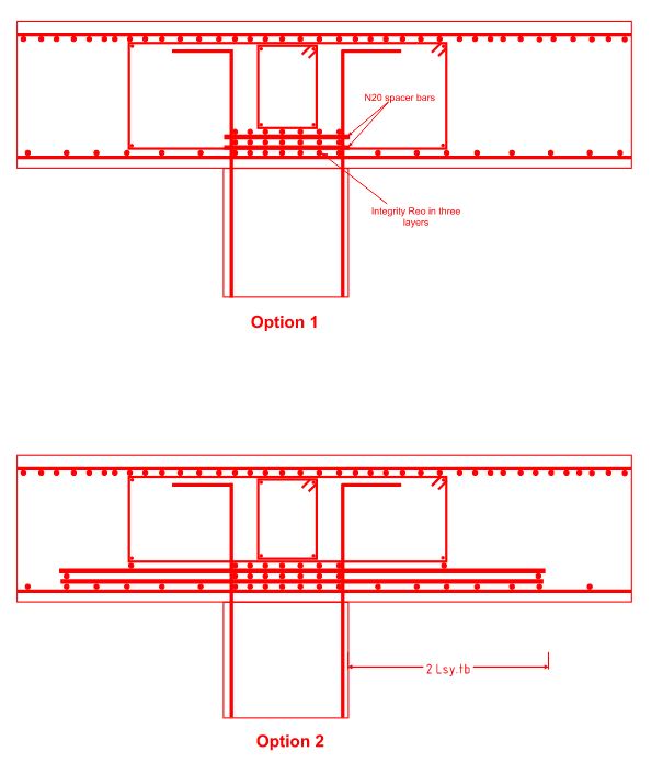
I have a 850 flat plate slab which I'm struggling to fit the integrity reo into the column cores. I had the idea of stacking the bottom bars in multiple layers and have drawn up two different arrangements which I think may be acceptable for this.
Option 1 is by far the easiest for the fixers on site. The idea is to stack the bars in the long edge of the column and separate using N20 spacers (to suit 20mm aggregate) in the short edge. My concern with this is that the reo will not be evenly divided on all edges, particularly since the slab mainly spans on the short edge of the columns (Typical for carpark transfers). The other concern is whether the stacked bars will realistically be able to contribute to the failure ductility in this arrangement.
Option 2 I believe remedies some of my concerns above by evenly distributing the integrity reo amongst each edge - but adds a lot of complexity which I don't trust the guys on site to do properly.
I'm open to exploring other options if my sketches are not within the intent of the code, however the slab is irregularly shaped so I can't get a beam grid in this particular case and the columns are limited by the carpark/traffic dimensions so I don't have a lot of wiggle room there either.
First time poster so please go easy on me. Because integrity reo is relatively new to Australian standards my supervisors are not a lot of help for me here.
I have a 850 flat plate slab which I'm struggling to fit the integrity reo into the column cores. I had the idea of stacking the bottom bars in multiple layers and have drawn up two different arrangements which I think may be acceptable for this.
Option 1 is by far the easiest for the fixers on site. The idea is to stack the bars in the long edge of the column and separate using N20 spacers (to suit 20mm aggregate) in the short edge. My concern with this is that the reo will not be evenly divided on all edges, particularly since the slab mainly spans on the short edge of the columns (Typical for carpark transfers). The other concern is whether the stacked bars will realistically be able to contribute to the failure ductility in this arrangement.
Option 2 I believe remedies some of my concerns above by evenly distributing the integrity reo amongst each edge - but adds a lot of complexity which I don't trust the guys on site to do properly.
I'm open to exploring other options if my sketches are not within the intent of the code, however the slab is irregularly shaped so I can't get a beam grid in this particular case and the columns are limited by the carpark/traffic dimensions so I don't have a lot of wiggle room there either.