Continue to Site

Eng-Tips is the largest engineering community on the Internet

Intelligent Work Forums for Engineering Professionals

  • Congratulations KootK on being selected by the Eng-Tips community for having the most helpful posts in the forums last week. Way to Go!

Interaction Diagrams For Wood Stud Walls 8

Status
Not open for further replies.

KootK

Structural
Oct 16, 2001
18,085
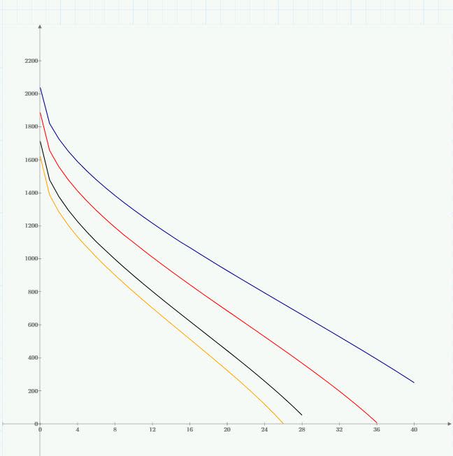
So I decided that I no longer wanted to be beholden to Woodworks etc and I would make my own stud wall MathCAD sheet. Go me. I wanted it done differently than what I see most folks do though. I wanted to generate interaction diagrams so that, for given project, I could just generate the diagrams for the handful of wall types that I'll use and then pick values from the graphs as needed. The graphs below do this I think. Each line is a different duration factor (0.9,1,1.25,1.6). They are for 2x4 stud grade 92.625" long; wind (psf) on the x-axis and axial (plf) on the y-ais. I've attached a printout of the entire worksheet for the ambitious.

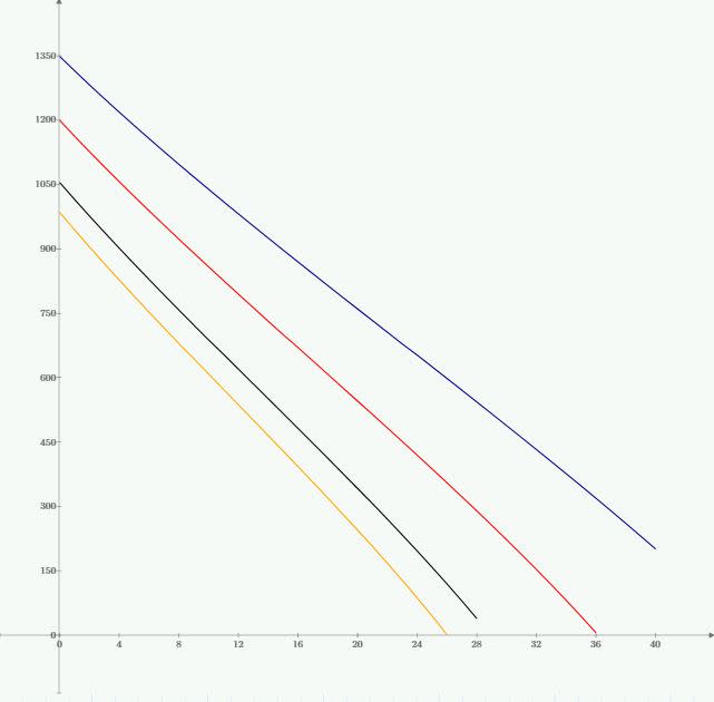
I've spot checked some results and they seem to be okay. What's bothering me is how straight these curves are. The only action is at the top left in the first diagram where things get curvy with low levels of wind pressure. If you include minimum axial eccentricity of d/6 like software often does, even that goes away. That's what's shown in the second graph below.

So my question is this: does anybody have enough experience with wood stud wall interaction diagrams that they could confirm or deny if the results I'm getting look nuts. Considering how straight the lines are, I would have thought that NDS would just simplify the equations to suit. Frankly, if it's this linear, I feel pretty silly for even going to the trouble of making this spreadsheet.
c01_pbi2dk.jpg

c02_kbseaw.jpg


I like to debate structural engineering theory -- a lot. If I challenge you on something, know that I'm doing so because I respect your opinion enough to either change it or adopt it.
 
Replies continue below

Recommended for you

c03_j2ppti.jpg


I like to debate structural engineering theory -- a lot. If I challenge you on something, know that I'm doing so because I respect your opinion enough to either change it or adopt it.
 
Your diagrams look accurate to me if your using wind pressure then with a weak horizontal pressures your likely going to be governed by the axial - DL+LL combination at the higher pressures your getting into being governed by the DL+0.75LL+0.75WL case pushing you to NDS 3.9.2 for the interaction which I believe is pretty close to a straight line interaction as only the compression strength term is squared, maybe also explains the abrupt dip from pure axial to first bending case.

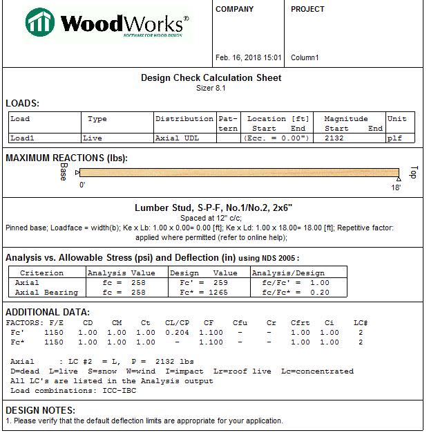
do your charts take into account plate crushing or the 5 psf minimum live load pressure?


Open Source Structural Applications:
 
Thanks for the feedback Celt. No plate crushing or 5 psf although I plan to add those once the base model’s up and running. Deflection too.

Presently, the graphs don’t even include load casing as I’m setting it up as a pure capacity monograph. The only load parameters in there are load duration and repetitive member.

I like to debate structural engineering theory -- a lot. If I challenge you on something, know that I'm doing so because I respect your opinion enough to either change it or adopt it.
 
I have wanted to make the same thing for quite some time now, but apparently my current method of calc'ing stud walls isn't inconvenient enough yet. I would imagine that a taller wall would result in a more nonlinear curve. If not, then I don't know why NDS doesn't linearize the design equations.
 
When I was in grad school, we had a question similar to this for the concrete code. My prof suggested we ask ACI about the why behind the way they did what they did. We got a great, detailed response.


I would be interested to hear what AWC says about this question.

Please remember: we're not all guys!
 
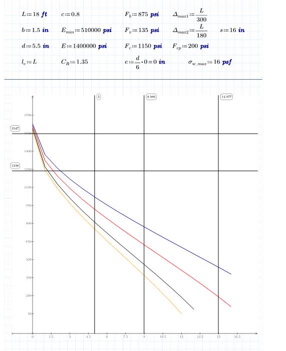
Revised version below. Things to note:

- Added some vertical marker lines corresponding to 5 psf and a couple of user defined deflection limits.
- Added some horizontal marker lines corresponding to sill plate crushing and sill plate crushing with the 1.25 increase.
- Tried out a long 2x6 SPF per Charlie. Same trend. Utterly liner if I put the d/6 eccentricity back in there.

Charlie said:
I have wanted to make the same thing for quite some time now, but apparently my current method of calc'ing stud walls isn't inconvenient enough yet.

You're certainly welcome to my stuff if you speak MathCAD. The sheet runs on the free version.

SLTA said:
I would be interested to hear what AWC says about this question.

We may get there but, first, I want to vet my output some more to make sure that it's not a KootK thang.

c01_yqp74z.jpg


I like to debate structural engineering theory -- a lot. If I challenge you on something, know that I'm doing so because I respect your opinion enough to either change it or adopt it.
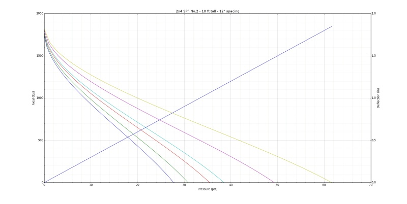
 
I've got a spreadsheet I've been meaning to convert over to python for wood wall/posts this seems as good a reason as any to knock it out over the weekend. A few minor edits in python and I can get similar output for comparison sake.

For deflection are you considering the min. eccentricity moment or just the lateral pressure?

Open Source Structural Applications:
 
Just the lateral pressure.

I like to debate structural engineering theory -- a lot. If I challenge you on something, know that I'm doing so because I respect your opinion enough to either change it or adopt it.
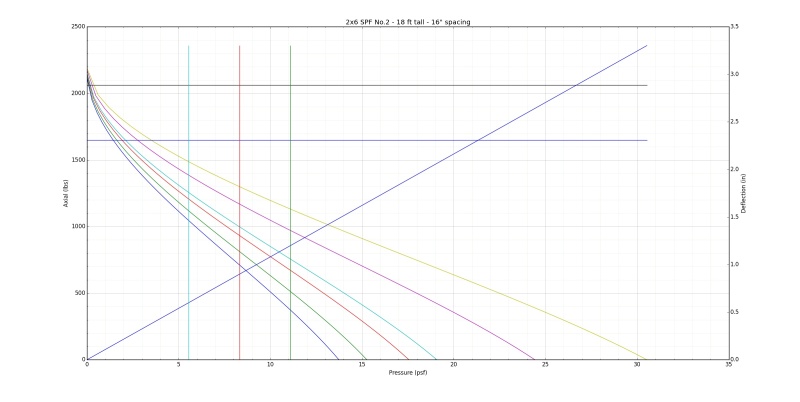
 
Bisection method... cool. Thanks so much for doing this Celt! Definitely above and beyond. I'm a little jealous that your stuff looks cooler than my stuff but, mostly, I'm just happy that we seem to be coming up with identical trends.

An interesting feature of these graphs is the steep rise in axial capacity as wind pressure and moment drop off. Inclusion of an eccentricity of d/6 straightens that portion of the graph out entirely which gives me the impression that consideration of some axial eccentricity is wise.

I like to debate structural engineering theory -- a lot. If I challenge you on something, know that I'm doing so because I respect your opinion enough to either change it or adopt it.
 
Yeah visualizing it and seeing the steep drop from pure axial to any bending whatsoever has me leaning towards adopting some form of minimum eccentricity on walls in the future.

for most my "goal seek" stuff so far I don't anticipate any inflection points so bisection method works well enough and with reasonable computation time for my needs and well if I'm being honest I coded it once got it to work and basically tweak than initial function to fit my new needs.

Open Source Structural Applications:
 
Some questions about your graph:

1) What condition does the diagonal line represent?

2) The defection scale on the right. Mispan deflection due to load eccentricity? The graph itself doesn't seem to include that.

I want these sexy features for my graph but first I need to figure out what they are.


I like to debate structural engineering theory -- a lot. If I challenge you on something, know that I'm doing so because I respect your opinion enough to either change it or adopt it.
 
The diagonal line is midspan deflection for the lateral pressures only.

Top horizontal line is plate crushing with Cb applied. Bottom line is plate crushing where Cb=1.

Vertical lines are l/360, l/240, l/180 deflection limits.

I'm about 75% thru programming a gui for this as well. Added in Fire Retardant option last night will also be adding in shear check and min ecc. Inclusive of deflection.

Open Source Structural Applications:
 
Any chance you're in the market for a protege? At the risk of boasting, I'm a kick ass programmer and love nothing more than developing structural applications. Unfortunately, I've come to the realization that anything worthy of my effort is going to need to be presentable as an online app I've not been able to spare the time to update my skill set to that. I could really use somebody who knows how to get it done to guide my efforts in learning & developing. Based on this and other threads, I feel as though you have similar interests and might be my guy. No serious pressure though. We're all to busy for extracurriculars.

I like to debate structural engineering theory -- a lot. If I challenge you on something, know that I'm doing so because I respect your opinion enough to either change it or adopt it.
 
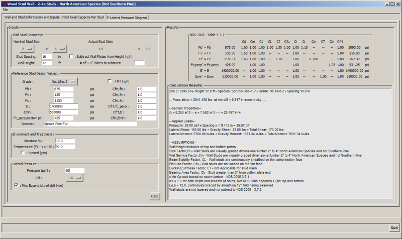
Basic GUI is functional will be adding the interaction graph to the second tab. The GUI is setup to calc the axial capacity based on the shown inputs. There isn't a whole lot of input validation so be mindful of inputs.
added Fv and Fv' calcs to the base wood wall class

here is an example of what the GUI looks like:
gui_nea0c9.png


Koot I'm probably not the one to lean to for any program learning I picked python up just a little over a year ago and have been mostly brute forcing my way thru things so not the most elegant or efficient coding. I keep meaning to really dig into the web application side of things but just don't have the time to invest in that right now which is a bit of a bummer. That being said I am always open to helping out just hit me up at the email in my profile.

I'll also throw in the learn python hat, it was a pretty easy transition from excel VBA and some small c++ on my end to python and it so much easier to read. The GUI's I build using TKinter which is very similar to VBA forms.

I have a co-worker who is a bit of a savant with this kind of stuff, hes been big into Jupyter Notebooks lately which supports lots of languages and looks like it might end up filling that web app hole.

Open Source Structural Applications:
 
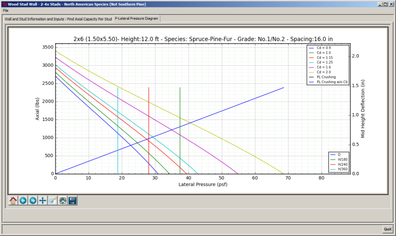
OK the GUI now has the full charting functionality.
I'll stop flooding the forum with update posts now, I plan to keep tweaking this check the commits on github if your interested as it will highlight what lines I've changed and I personally like to include comments with each commit stating some change log info:
Hopefully Near Future updates:
-give additional results information like the stresses, interactions, detailed Cp calculation steps in the results text box and give it horiz/vert scroll bars so you can see all the info
-Add the ability to save all the user inputs and open a file with those inputs
-Write out a results text file - likely comma separated for easy import into excel
-plot the deflection with the eccentricity considered and solve for the P-M combinations that yields each deflection limit so those vert lines fall in the proper location on the chart.
-Input validation - ugh not my favorite process

The plate crushing horizontal lines will only show up if they are less than 20% greater than the maximum axial load with Cd=2.0
Capture_cyox8c.png


Open Source Structural Applications:
 
Celt83... what programming language did you use for the GUI?

Dik
 
Status
Not open for further replies.

Part and Inventory Search

Sponsor