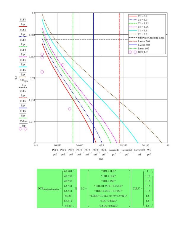
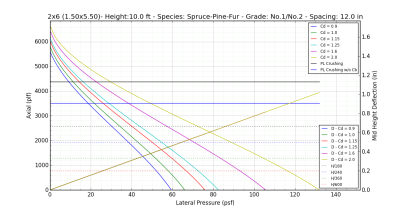
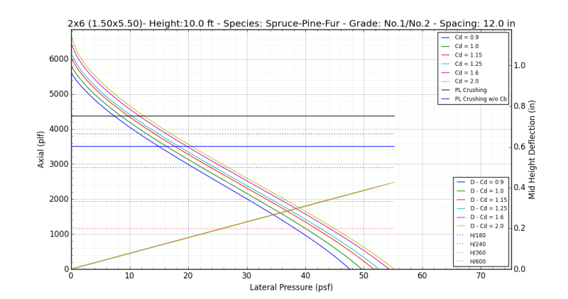
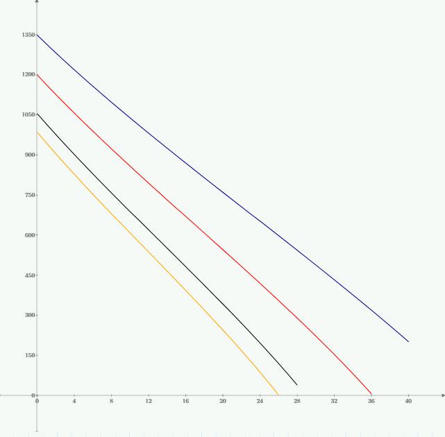
So I decided that I no longer wanted to be beholden to Woodworks etc and I would make my own stud wall MathCAD sheet. Go me. I wanted it done differently than what I see most folks do though. I wanted to generate interaction diagrams so that, for given project, I could just generate the diagrams for the handful of wall types that I'll use and then pick values from the graphs as needed. The graphs below do this I think. Each line is a different duration factor (0.9,1,1.25,1.6). They are for 2x4 stud grade 92.625" long; wind (psf) on the x-axis and axial (plf) on the y-ais. I've attached a printout of the entire worksheet for the ambitious.
I've spot checked some results and they seem to be okay. What's bothering me is how straight these curves are. The only action is at the top left in the first diagram where things get curvy with low levels of wind pressure. If you include minimum axial eccentricity of d/6 like software often does, even that goes away. That's what's shown in the second graph below.
So my question is this: does anybody have enough experience with wood stud wall interaction diagrams that they could confirm or deny if the results I'm getting look nuts. Considering how straight the lines are, I would have thought that NDS would just simplify the equations to suit. Frankly, if it's this linear, I feel pretty silly for even going to the trouble of making this spreadsheet.
I like to debate structural engineering theory -- a lot. If I challenge you on something, know that I'm doing so because I respect your opinion enough to either change it or adopt it.
I've spot checked some results and they seem to be okay. What's bothering me is how straight these curves are. The only action is at the top left in the first diagram where things get curvy with low levels of wind pressure. If you include minimum axial eccentricity of d/6 like software often does, even that goes away. That's what's shown in the second graph below.
So my question is this: does anybody have enough experience with wood stud wall interaction diagrams that they could confirm or deny if the results I'm getting look nuts. Considering how straight the lines are, I would have thought that NDS would just simplify the equations to suit. Frankly, if it's this linear, I feel pretty silly for even going to the trouble of making this spreadsheet.


I like to debate structural engineering theory -- a lot. If I challenge you on something, know that I'm doing so because I respect your opinion enough to either change it or adopt it.

