Continue to Site

Eng-Tips is the largest engineering community on the Internet

Intelligent Work Forums for Engineering Professionals

  • Congratulations KootK on being selected by the Eng-Tips community for having the most helpful posts in the forums last week. Way to Go!

Interaction Diagrams For Wood Stud Walls 8

Status
Not open for further replies.

KootK

Structural
Oct 16, 2001
18,244
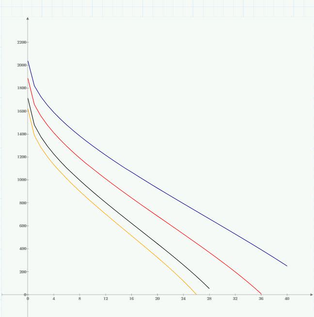
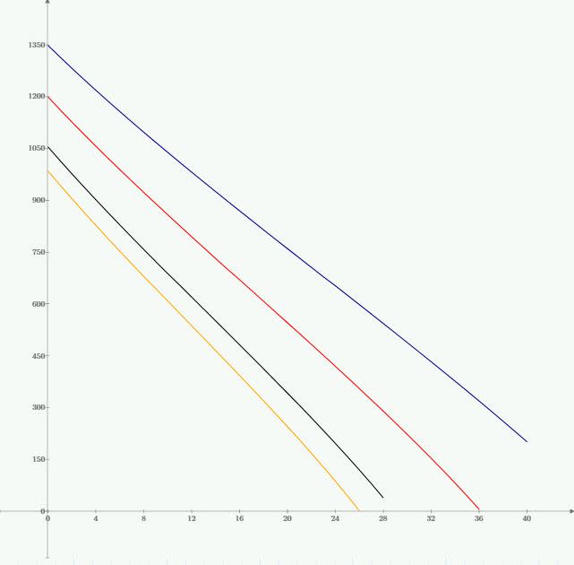
So I decided that I no longer wanted to be beholden to Woodworks etc and I would make my own stud wall MathCAD sheet. Go me. I wanted it done differently than what I see most folks do though. I wanted to generate interaction diagrams so that, for given project, I could just generate the diagrams for the handful of wall types that I'll use and then pick values from the graphs as needed. The graphs below do this I think. Each line is a different duration factor (0.9,1,1.25,1.6). They are for 2x4 stud grade 92.625" long; wind (psf) on the x-axis and axial (plf) on the y-ais. I've attached a printout of the entire worksheet for the ambitious.

I've spot checked some results and they seem to be okay. What's bothering me is how straight these curves are. The only action is at the top left in the first diagram where things get curvy with low levels of wind pressure. If you include minimum axial eccentricity of d/6 like software often does, even that goes away. That's what's shown in the second graph below.

So my question is this: does anybody have enough experience with wood stud wall interaction diagrams that they could confirm or deny if the results I'm getting look nuts. Considering how straight the lines are, I would have thought that NDS would just simplify the equations to suit. Frankly, if it's this linear, I feel pretty silly for even going to the trouble of making this spreadsheet.
c01_pbi2dk.jpg

c02_kbseaw.jpg


I like to debate structural engineering theory -- a lot. If I challenge you on something, know that I'm doing so because I respect your opinion enough to either change it or adopt it.
 
Replies continue below

Recommended for you

I'm not familiar with Python, and, was just curious... you can do similar GUI with Visual Basic, Visual C, and Delphi... I prefer a GUI with less indents... but, looks good.

I didn't realise that Python was that evolved...

Dik
 
yeah Python is much more evolved then I remember when I first heard about it, there is a small hit to computation time on the more complicated things. I hear ya on the indents - I could spends days/months tweaking the visual appearance now that I have my input and output structured.

Open Source Structural Applications:
 
Celt83 said:
I'll stop flooding the forum with update posts now

Don't hold back on my thread's account. You've answered my question more convincingly than I could have hoped for. And this is interesting.

I like to debate structural engineering theory -- a lot. If I challenge you on something, know that I'm doing so because I respect your opinion enough to either change it or adopt it.
 
Using SMath Studio, I'm having difficulty in defining new units... the attached code shows that a, and b in inches when multiplied provides an answer in m^2... not really useful. Can someone show me how to do this so the resulting units are in^2... I've tried about 20 approaches without success.

Dik
 
 http://files.engineering.com/getfile.aspx?folder=fdaa22d0-e62e-4c07-be6a-35c66b817727&file=Example.sm
KootK:
If you insist :)

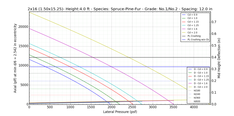
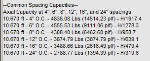
made a bunch of additions the output now includes capacities at various stud spacings, added a P-M curve which is nearly identical to the P-Pressure Curve with the exception that it plots mid height deflection inclusive of the eccentric moment.

See it in Action: full res animated gif

Common Capacities:
Capture_xjxyrx.jpg


For those hesitant to install python I have compiled the gui to run stand alone on windows systems: OneDrive
it is a 50mb +/- zip file that will uncompress to nearly 140 mb
there will be a lot of files the one to run the gui is this one:
run_me_d5yphj.jpg

The first time you run it will take a few seconds so be a bit patient please

Dik:
Not overly familiar with SMath studio but did dig a bit the last time I saw it mentioned. Have you edited the Units.xml file or did you define the in*in relationship in your specific file?

Open Source Structural Applications:
 
Tried to do it in the new program file... Didn't know about Units.xml file. We'll take a gander...

Dik
 
added the ability to export the results as a text file.
Gives you two files a CSV file of the NDS load reduction factor table and a pure text file of the results text box
Everything is saved on your desktop in a 'RESULTS' folder
file_output_qayxi1.jpg


Compiled File: OneDrive
source code is on my github - linked in my signature


Open Source Structural Applications:
 
I managed to define in^2 in terms of m^2... thanks... I'll have to see how Units.xml is formatted.

Does your program run as an actual *.exe? or as an interpreted tokenised file? Does Python (an interpreter) create a true executable? The exe should run a lot faster.

Dik
 
Dik:

It runs as an executable(.exe) however if I understand how the compiler I use works correctly the exe file at launch essentially does a real time compile of my python file and all it's associated python files which is why there is a pretty decent delay before you as the end user will see the gui show up, this is mostly because I am using matplotlib for the embedded charts as it has a decent amount of dependencies.

In other words I think your second option it does some form of a tokenized executable.

Open Source Structural Applications:
 
Really great looking program... a lot of effort... and much appreciated. Looked into Python as well as xml programming/scripting... a star for you and kootk...

Dik
 
new version uploaded:
Corrections:
-Deflection calculations for the P-M curve where not correct, the P-M curve was multiplying the plf value by the spacing's inflating the deflection numbers
-Cf was not being calculated for Stud grade lumber greater than 6" nominal depth, per NDS Table Cf should be per No.3 grade when depth is 8" or greater

Additions:
-addition of H/180,240,360,600 horizontal lines to both charts
-addition of eccentric load mid height deflection to P-Pressure Chart
-Automatic generation of PvPressure, and PvM curves for common spacing's of 4",6",8",12",16", and 24". Charts are saved as 11x17 pdfs in the results folder
-Results and Chart file names will indicate if Axial eccentricity was considered

Changes:
-chart y-axis is now in units of lbs/ft (plf)

Open Source Structural Applications:
 
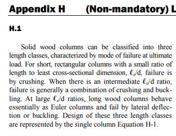
Think Appendix H is shedding some light on the behavior:
Capture_hgt14n.jpg


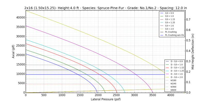
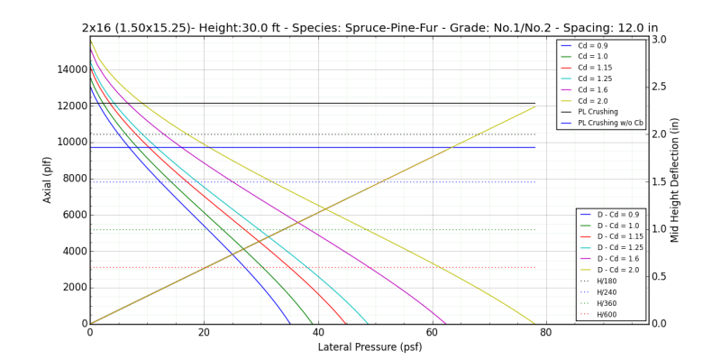
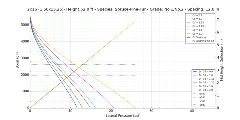
using my 2x16 stud at 12 in as an example - stresses below assume 20 psf and Cd=1.6:
no eccentricity
4ft tall:
Code:
fc = P/A = 1552.830 psi
fv = VQ/Ib = 3V/2bd = 2.623 psi
fb = Mc/I = M/s = 6M/bd^2 = 8.256 psi
Combined Axial+Bending:
[fc/Fc]'^2 + fb / Fb' [ 1- (fc / FcE)] = 1.000 <= 1.0
Ke * le,d / d = 3.148 in < 50
very low bending stress relative to axial stress therefore squared term of combined check controls - short column
short_jjmxii.png


30ft tall:
Code:
fc = P/A = 386.944 psi
fv = VQ/Ib = 3V/2bd = 19.672 psi
fb = Mc/I = M/s = 6M/bd^2 = 464.391 psi
Combined Axial+Bending:
[fc/Fc]'^2 + fb / Fb' [ 1- (fc / FcE)] = 1.000 <= 1.0
Ke * le,d / d = 23.607 in < 50
Intermediate column
intermediate_gttog7.png


52ft tall:
Code:
fc = P/A = 8.959 psi
fv = VQ/Ib = 3V/2bd = 34.098 psi
fb = Mc/I = M/s = 6M/bd^2 = 1395.238 psi
Combined Axial+Bending:
[fc/Fc]'^2 + fb / Fb' [ 1- (fc / FcE)] = 1.000 <= 1.0
Ke * le,d / d = 40.918 in < 50
Bending Controlled - non-squared term of combined check governs
tall_n2ahq2.png


now looking at the 4ft tall wall again with d/6 eccentricity:
Code:
Pmax,allow = 19464.43 lbs (19464.43 plf)  at min d/6 = 2.542 in eccentricity
--Applied Loads--
Pressure: 20.00 psf x Spacing x 1 ft / 12 in = 20.00 plf
Lateral Shear: 40.00 lbs + Gravity Shear: 1030.67 lbs = Total Shear: 1070.67 lbs
Lateral Moment: 480.00 in-lbs + Gravity Moment: 49472.09 in-lbs = Total Moment: 49952.09 in-lbs
Lateral Delta: 0.000 in + Gravity Delta: 0.011 in = Delta: 0.012 in - H / 4115.3

--Stresses--
fc = P/A = 850.904 psi
fv = VQ/Ib = 3V/2bd = 70.208 psi
fb,lat = Mc/I = M/s = 6M/bd^2 = 8.256 psi + fb,gravity = 850.904 = 859.160
Combined Axial+Bending w/ Eccentricity:
[fc/Fc]'^2 + (fb,lat + fc(6e/d)[1 + 0.234 (fc / FcE)])/ Fb' [ 1- (fc / FcE)] = 1.000 <= 1.0
Ke * le,d / d = 3.148 in < 50
fb >> fb,no ecc. non-squared term in combined equation begins to govern much sooner if not immediately
short_ecc_dm6yg1.png


Open Source Structural Applications:
 
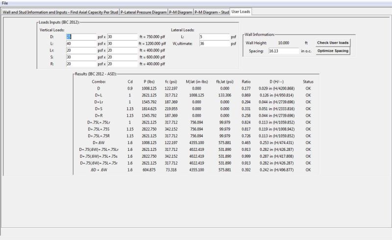
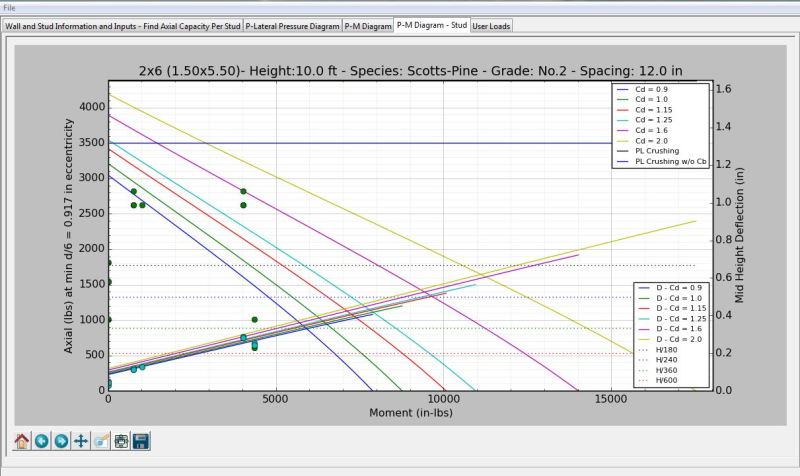
user loads and IBC 2012 load combinations implemented and also added ability to optimize stud spacing for user loads. Use loads are plotted on the PvM-stud curve.

User Loads Tab:
Capture_qcdd0g.jpg


PvM-Stud Tab:
Capture2_pkfype.jpg


all links updated


Open Source Structural Applications:
 
You deserve a whole bunch of stars for the effort.

Dik
 
correction:
-User Loads - Interaction ratio corrected to be checked against fc/Fc' when M=0 and fb/Fb' when P=0 for case when min. eccentricity is not included.

a current base assumption is fv/Fv' won't control but I'm going to add that check in just as a catch all. plan to update the ratio text to indicate what NDS equation it checked against/controlled to make manual back checks easier. So next update the ratio text will read something like
Code:
.762 (eq. 15.9-1)

edit: apparently when I said future updates I meant in the next half hour
all links updated
Open Source Structural Applications:
 
enhancements:
-(2)2x and (3)2x stud options added per NDS 15.3.2 Cp for properly connected built up columns is Kf * Cp base assumption for stud walls is sheathing provides full bracing to the short face so Kf is per Le1/d1 so = 1.0. therefore properly nailed/bolted built up 2x studs can be calculated as if they are a solid section.
-spacing optimization will not provide spacing smaller than the actual stud width and will now report spacing's to the nearest lower bound 1/4"

additions:
-clarified wall height assumption to indicate design stud height is either wall height or wall height - (x) 1.5" plates
-updated base assumptions to note capacity is inclusive of wall self weight, true supporting capacity is (result - panel self weight)
-self weight is now a user vertical load category - height can be larger than the wall height, useful when looking at multi story walls

correction:
-user loads that produced points where fc > FcE were mistakenly marked as OK as the interaction ratio was -x so less than 1, additional check for fc < FcE added ratio text will indicate if fc>FcE - "100 (fc > FcE)"

Open Source Structural Applications:
 
Hell yes. Hail to the nomograph! My updated thoughts on this:

- As far as I know, this is now the best wood stud wall design tool available on planet earth, P4P or otherwise.

- This, combined with Forte for beams, basically makes it so that I no longer have need of wood specific commercial software.

- You should really reconsider my offer of collaboration. Within this space, I plan to a) have some serious fun b) give back to the SE community substantially c) earn a little passive income. And you're clearly the man for the job. I don't by this "I'm a hack but my friend's really good" business. It if sweetens the deal, I think that I've got another ET'er lined up for the team.

I like to debate structural engineering theory -- a lot. If I challenge you on something, know that I'm doing so because I respect your opinion enough to either change it or adopt it.
 
Status
Not open for further replies.

Part and Inventory Search

Sponsor