Hey All,
Y14.5 R2018 permits the use of continuous feature on external planar surfaces now.
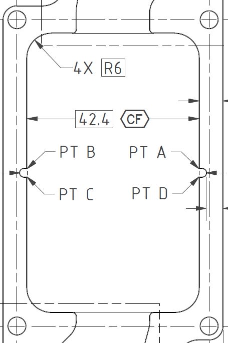
However, my engineer's drawing I'm reviewing has applied it internally.
Intrinsically, this makes sense in what it intends, but it's not explicitly explained from what I could read in our book so I prefer not to use it. (No salt please: I don't have a PDF where I can Crtl+F and search the whole standard quickly, and we all know the lack of an index in the book is a wild oversight)
Secondly, I didn't see anything about adding continuous feature to a basic dim either. It doesn't seem proper, but a profile tolerance is also applied (hence the points), so without a continuous feature symbol it would be ok with what I know.
Here's a picture of what I'm talking about:

There's a variety of methods I can use to convey what we want in the real world, but I know why my engineer chose this: Less dims and control frames to add to the drawing. I really wanted to open a discussion on this to see what others think.
If I present my design review correctly, this more complicated design will be eradicated, but I need some backup as there's no GD&T SME I can consult at our company.
Thanks!
Y14.5 R2018 permits the use of continuous feature on external planar surfaces now.
However, my engineer's drawing I'm reviewing has applied it internally.
Intrinsically, this makes sense in what it intends, but it's not explicitly explained from what I could read in our book so I prefer not to use it. (No salt please: I don't have a PDF where I can Crtl+F and search the whole standard quickly, and we all know the lack of an index in the book is a wild oversight)
Secondly, I didn't see anything about adding continuous feature to a basic dim either. It doesn't seem proper, but a profile tolerance is also applied (hence the points), so without a continuous feature symbol it would be ok with what I know.
Here's a picture of what I'm talking about:

There's a variety of methods I can use to convey what we want in the real world, but I know why my engineer chose this: Less dims and control frames to add to the drawing. I really wanted to open a discussion on this to see what others think.
If I present my design review correctly, this more complicated design will be eradicated, but I need some backup as there's no GD&T SME I can consult at our company.
Thanks!
