Eng-Tips is the largest engineering community on the Internet

Intelligent Work Forums for Engineering Professionals

Internal snap ring with three control dimensions problem 6

Status
Not open for further replies.

Znjmech

Mechanical
Dec 19, 2016
94
0
0
IT
Hi all

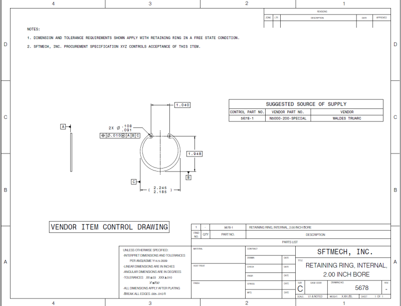
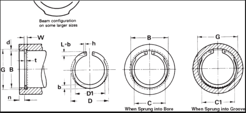
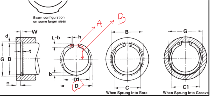
For an internal snap ring with two grip holes that we get from a supplier, we need to control three dimensions and it seems hard that all of these parameters come right at the same time. The dimensions interested are: the horizontal inter-axis of the two holes, the vertical inter-axis between the holes and the center of the ring and the Ring diameter. There's also a spring back included.
regarding to the production method of the ring that I don't think that would be more than one method, is there any control method during production to apply to avoid these diameters go into discordance with the required?

snap-ring_cgwcnw.png
 
Replies continue below

Recommended for you

If the bore G is correct, the lock ring will be snug in the groove when assembled.

If the Bore B is correct, the plier holes will be accessible after the ring is installed, AND the ring can be squeezed small enough to install, without the ends butting.

The attached image shows a dimension that directly controls whether the plier holes will be accessible after the ring is installed.
I think this is related to the dimensions you are questioning.

Are the rings you have received giving you installation problems?
 
 http://files.engineering.com/getfile.aspx?folder=48e29bf8-e4e7-4958-ab43-97502d55852b&file=snap_ring_hole_edge_diimension.png
Here is the updated image.

@Tmoose: yes we got installation problems, There are grips to hold the holes. not so flexible. The dimension T doesn't guarantee the gap between the holes and their distance from the Ring center. The dimension T seems very hard to control, what method would you propose (despite that I don't think that it would guarantee the other dimensions)

snap-ring_igferz.png
 
The Truarc installation tool instructions describes an adjustable stop on the tool to be set to allow easy, reliable pick up of the free ring. When squeezed the tool will close the ring sufficiently to pass through the noted bore B during installation. The tool tips are sufficiently smaller than the holes in the ring to allow removal of the tool after the ring is installed in the specified groove diameter G.

SFTmech, what procedure are you using to install the retaining ring that requires knowing precisely the hole locations?

Ted
 
SFTmech-

Here is the procurement standard for mil-spec retaining rings. The retaining rings produced to this standard have been widely used over the 50+ years it has existed. Might provide some answers to your questions regarding dimensional control of the ring features and the inspection procedure used for acceptance.

You mentioned an issue with your installation tool's pre-set grip position properly engaging the mating holes in your retaining rings. The first thing to consider is that the type of internal retaining ring you show is typically produced by die stamping. So the hole locations are set by the tooling, and should be very consistent on every part made from a particular tool. The procurement standard linked above lists a free state end gap dimension 'K' in table 1 for an internal ring, and if you look at the tolerance range for this dimension you'll note that it is quite large. I don't recall seeing any standard that controlled the exact hole locations, but they are usually near the ring ends. Given the large tolerance range allowed by the standard for the free state end gap, it's easy to imagine the free state hole positions also varying widely. If you haven't done so already, there is some tech information regarding production installation tooling on the Waldes Truarc website.

If you really need a standard retaining ring design with positional control of the tool holes, most manufacturers like Waldes Truarc will provide them. All you need to do is order their standard part with an added requirement for dimensional control of the free state hole locations.
 
Thank you for your reponses

The installation is not manual , so the instructions wouldn't help me . tbuelna, all of the snaps in the first link had other parts as control dimensions. like the head width.
 
You may want to consider an installation method similar to that shown in this Smalley link.

Arrange a plunger to push the retaining ring into and through a tapered bore sleeve which compresses the retaining ring to or smaller than your target bore leading to the retaining ring groove. Then there is no need to know the dimensions for which you have concerns.

Ted
 
Thank you Hydtools

The question is not putting the snap ring in its position, but to lifting it up by a fixed fork ( containing two pins to hold the holes)
 
How does the thickness of the ring (dimension "t" you referred to above) affect your ability to get the tool into the holes for removal of the snap ring?
 
At this point the question requires pictures of the entire desired process. If it is something that even the makers of snap rings and snap ring automation haven't dealt with then everyone else is going to need a better description.

You can go to to get all the related specifications for MIL-DTL-21248.
 
SFTmech-

The point I was making is that industry or mil standards for the type of retaining ring shown do not provide specific dimensional location control of the tool holes. Instead, each manufacturer can locate the holes where they choose, provided the ring meets all of the standard requirements. Basically what you're asking for is a standard vendor item with an additional requirement for location control of the tool holes. This situation is actually fairly common, and is typically handled using something called a Vendor Item Control Drawing. You can find an example of a Vendor Item Control Drawing in ASME Y14.24-2012 (fig.10-2).

If you look at the drawing example, you'll see views of a standard vendor part with some additional dimensional control requirements. On the right side of the drawing you'll see a table listing the vendor name and vendor part number for procuring this item. Before making this drawing, you will need to contact a vendor willing to supply a retaining ring conforming to your requirements. And most vendors are happy to do this. Tell them that you want their standard part with an additional requirement for positional control of the tool holes. Ask them for the hole location dimensions/tolerances they can meet in quantity for rings in a free-state condition, and dimension your drawing accordingly. The vendor will also provide you a custom part number for ordering this part.

Using a Vendor Item Control Drawing to procure your retaining rings will ensure control of the tool hole locations you require. It should not add much cost since you are not altering the vendor's standard design. Instead, you are simply asking for confirmation that the items delivered conform to specifications not defined in their published information for the standard part.
 
tbuelna Thank you so much for your super answer. while I have yet to understand its relation, that how it would help me. Yes we have our required dimensions that simulate the lifting mechanism that's very rigid. the holes could go out of tolerance due to manufacturing method. coiling. that's the problem

Ted : you are a genius. Period
 
This type of ring is stamped out, not coiled. The hole locations for snap rings are created by piercing pins in the tooling.
It sounds like the design of your assembly equipment is not able to work with commercially toleranced components- this is the sort of thing that should have been part of the equipment build specs.

You may have some trouble finding a source for your specially controlled retaining rings unless your have some significantly high volume- controlling the hole location tighter than normal may be challenging for many ring vendors.
 
@Screwman

as far as I know, the ring is first coiled, then the holes are stamped out. the spring back before the stamping determines the in tolerance zone or out of tolerance zone.

What did you mean by "source" ? a manufacturer?
 
Retaining rings can be either coiled or stamped- but the type shown in your drawing is very clearly a stamped ring.

Coiled retaining rings look like this:

retaining-rings.jpg


Notice that the wire used to make these rings is the same cross section throughout the ring. They can have bent features or holes to interface with tools, but the cross section of the wire is consistent throughout.

This type of ring is typically made from special trapezoidal wire, so that the metal flow during coiling results in a ring with a rectangular cross section.

Stamped rings look like this:

URL]


Notice that the ears where to tool features are located are not the same cross section as the rest of the part, and that for internal rings there is a change in cross section- opposite the opening the cross section is wide, and it then tapers toward the ears.

It would probably be possible to coil a ring and then form the cross section into this shape, but it would be much more expensive than just stamping them out of sheet, which is why they are stamped.

If your drawing is accurate, you're buying stamped rings.
 
SFTmech said:
tbuelna Thank you so much for your super answer. while I have yet to understand its relation, that how it would help me.

To help you understand how procuring your retaining ring using a Vendor Item Control Drawing approach will ensure the tool hole position is controlled and consistent, I spent 15 minutes making the sample drawing attached. The example part is a standard Waldes Truarc 5000 series internal retaining ring for a 2.00" bore. All of the reference dimensions shown can be found on their website. The basic dimensions and positional tolerance shown are for illustration purposes only, and you must get the correct values from Waldes Truarc engineering.

I hope this explains how this approach for procuring retaining rings will allow you to design an assembly tool that always interfaces properly. The approach does not require any changes to the tooling or manufacturing process used by Waldes to produce this standard part. Basically, all it does is ensure
vendor_item_control_drawing_uxef6m.png
that Waldes (or any other vendor) does not deliver a "standard" part that has been modified in some way that will affect your existing manufacturing process/tooling.
 
Jgkr thank you so much for your instructive ansser.
That's strange, the rings look like the stamped ones, but the supplier talked also about the coiling before stamping.
Tbuelna thank you very much. Well in your example, you have displaced the plane B from the center to the perimeter. Does it change a lot of things?
 
Tbuelna, you get a star.

SFTmech, the datun B makes a reference for a physical measurement rather than to a non-existant center point found by inference of a diameter.

Ted
 
Status
Not open for further replies.
Back
Top