Continue to Site

Eng-Tips is the largest engineering community on the Internet

Intelligent Work Forums for Engineering Professionals

  • Congratulations KootK on being selected by the Eng-Tips community for having the most helpful posts in the forums last week. Way to Go!

Internal snap ring with three control dimensions problem 6

Status
Not open for further replies.

Znjmech

Mechanical
Dec 19, 2016
94
Hi all

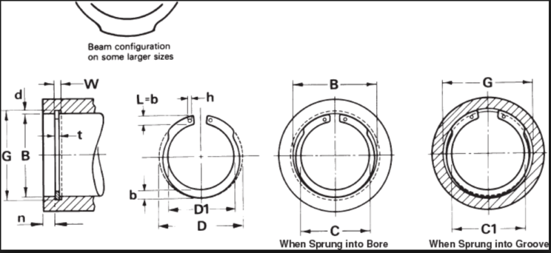
For an internal snap ring with two grip holes that we get from a supplier, we need to control three dimensions and it seems hard that all of these parameters come right at the same time. The dimensions interested are: the horizontal inter-axis of the two holes, the vertical inter-axis between the holes and the center of the ring and the Ring diameter. There's also a spring back included.
regarding to the production method of the ring that I don't think that would be more than one method, is there any control method during production to apply to avoid these diameters go into discordance with the required?
snap-ring_cgwcnw.png
 
Replies continue below

Recommended for you

For material waste control I can imagine using coiling to produce a semi-circular blank and then stamping the entire profile from that. The other type of ring is simply coiled where the active perimeter remains and only installation details are stamped.

This would have the advantage of aligning the grain orientation with the shape of the ring instead of continuously varying with cross-section as it would if stamped from strip. This would not likely be used for E-rings but for the ordinary ones.
 
SFTmech said:
Tbuelna thank you very much. Well in your example, you have displaced the plane B from the center to the perimeter. Does it change a lot of things?

Based on your previous posts it seemed that your issue was controlling position of the holes so that the ring could be grasped by the pins of an automated installation tool. Logically, the retaining ring would be in a free-state condition when it is grasped by the automated installation tool. So a free-state condition is what should be defined on your Vendor Item Control Drawing, and that is clearly stated in general note 1 on the drawing example provided.

The type of internal retaining ring shown does not have a circular outer profile in a free-state condition. It has a free-state outer profile designed to provide a uniform circumferential radial pressure and conformal fit with the groove OD when installed. Since the ring free-state outer profile (as shown in the drawing example) has no symmetry about a horizontal axis, there is no "center" location in the vertical direction. As hydtools noted, in this situation it makes sense to dimension from a physical surface. There might be a better approach for interface control dimensions than what I used in the drawing example, but I'm sure it explains the basic concept.

Hope that helps.
Terry
 
3DDave said:
For material waste control I can imagine using coiling to produce a semi-circular blank and then stamping the entire profile from that. The other type of ring is simply coiled where the active perimeter remains and only installation details are stamped.

This would have the advantage of aligning the grain orientation with the shape of the ring instead of continuously varying with cross-section as it would if stamped from strip. This would not likely be used for E-rings but for the ordinary ones.

Certainly possible. Come to think of it, the grain orientation is a consideration I hadn't thought of before- I would bet that they are coiled first as you describe.

I would imagine this doesn't have much effect on the final dimensions and their consistency, since hole spacing and profile is still set by the stamping die.
 
Status
Not open for further replies.

Part and Inventory Search

Sponsor