Continue to Site

Eng-Tips is the largest engineering community on the Internet

Intelligent Work Forums for Engineering Professionals

  • Congratulations IDS on being selected by the Eng-Tips community for having the most helpful posts in the forums last week. Way to Go!

Interpreting profile of a surface 2

Status
Not open for further replies.

sendithard

Industrial
Aug 26, 2021
179
Am I interpreting the profile of a surface callouts correctly. The tighter tolerance is only referencing datum AE. So am I correct this tighter tolerance only affects the red lines as seen below?

Thanks...

Capture_uwpl4b.jpg
 
Replies continue below

Recommended for you

sendithard,

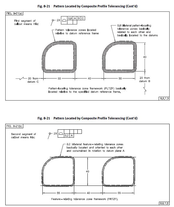
The all-around symbol is applied to the leader line so the profile applies all-around the indicated profile for all segments of the profile tolerance in question. Datum feature references do not change that - they only change the constrained DOF for each segment/tolerance zone. In this case, you have a composite tolerance so the lower frames (FRTZF) can only constrain rotational DOF wrt your DRF.

Do you have a copy of the Y14.5 standard? If not, its a worthwhile investment.

fig_8-21_u5q0af.jpg
 
Chez,

I don't have a copy, but will consider getting one. In my above picture I highlighted in red all profile surfaces that I thought could be measured vs datum A&E. I understand the leader line circle says the entire profile shall be held to a tol zone....but how can a surface resting perpendicular to Datum E be measured against Datum E? That was why I didn't highlight that surface in red as I wouldnt know how to measure it against E. So I figured that surface would default back to the FCF using datum AED and hence those non-red surfaces would enjoy the benefit of the larger tol zone highlighted in blue.
 
sendithard,

Any profile can be measured/held to a tolerance zone regardless of whether it is parallel to, perpendicular to, or at any angle to the specified DRF. A surface that is perpendicular to a specified datum feature still has an orientation requirement that it must meet, even if it doesn't have location - in this case its just like a perpendicularity tolerance. How do you think perpendicularity tolerances are measured? Profile is a cumulative tolerance which controls all aspects of form, orientation, and location - if a feature does not have location defined to the specified DRF it still must meet the other two. Indeed the lower segment (FRTZF) of a *composite profile tolerance has no location constraint to the specified DRF by definition - only orientation, this being one of the key differences between a composite tolerance and multiple single segment. Even if no datum features are specified (datumless) you still have a form requirement it must meet.

Note that in your case we have a collection of features (technically a type of pattern) specified by the all-around symbol. This means they must be considered together, and the true profile is defined by the basic dimensions of these features, and the tolerance in this case is equally disposed about that true profile. Orientation/location/form of the profile is considered as a whole, not as separate surfaces.

If you can convince your employer to purchase the standard I would highly recommend it. Its not necessarily the best learning tool for everyone as an introduction to the concepts, but once you start having a working knowledge of the concepts having access to the primary source is really important, really a requirement in my mind. And if you have either internal or customer drawings which adhere to Y14.5 then you really need to have the standard on hand anyway, if you need to make a business case for it.

*Edited for clarity
 
Chez,

I'm still not fully grasping this composite profile tolerance. I've gone over our converstation carefully as well as pouring over some additional videos and material.

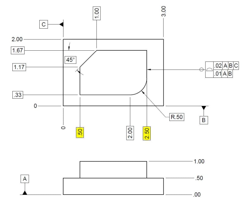
Below is a simplified drawing. From my understanding the top tolerance is the simple tol zone you would expect. So all around that upper vertical surface can deviate within the .02 tol zone.

Here is when I get confused. I think the bottom tol zone dictates the tol zone each feature can deviate from each other. If this statement is true then given there are no dimensions showing distances b/w the profiled surface would you just do the math from the existing basic dimensions? For instance just take the difference b/w the yellow dimensions and both those surfaces must hold to a zone of .01 from each other?

My next question would be since the bottom tol zone includes the A,B drf would the .33 dimension still be required to be measured within the tighter .01 zone b/c Datum B is in the drf...whereas if it were datumless would each surface just be held to each other without concern over distance from Datum B and perpendicularity to Datum A?

I've got a few more questions, but I would prefer to just baby step into getting past this hurdle.

Thanks.
COMPOSITE_ekc9t1.jpg
 
sendithard,

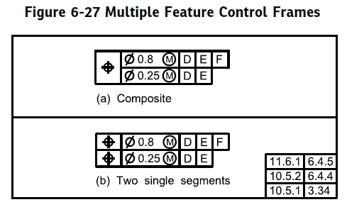
First off, just to get it out of the way before I make any assumptions since you already stated you do not have access to the standard I want to make sure I clearly define the difference between a composite and multiple single segment tolerance. A multiple single segment allows constraint of both translation and rotation in the lower segments, its basically just a special case of two or more separately applied profile (or position) tolerances. A composite tolerance, which you have shown here, does NOT allow constraint of translation in the lower segments (FRTZF) - ONLY ROTATATION. Ie: any location with respect to your datum features does NOT apply in the lower segments/FRTZF of a composite tolerance.

Note the differences in notation (in this case position, but of course same applies for profile):

composite2_w15mxl.png


Okay, so a few items which might help your understanding. First, basic dimensions are theoretically exact - period. It does not matter from what reference they are defined, as long as the geometry is fully defined somehow, the exact method makes no difference as long as it is clear. For example it does not matter if the highlighted dimensions are given as ordinate dimensions as shown from the left edge, as separate width dimensions wrt each other [0.5] and [2.0], or ordinate dimensions from the right edge the result is the same (assuming its okay the rightmost dimension can be basic, which its not currently).

Secondly, we use these basic dimensions for a profile tolerance to define our "true profile" - which is essentially just that, the theoretically exact geometry defined by basic dimensions. Your profile tolerance zone, is a zone of a width defined by your FCF in this case equally disposed about your true profile. The addition/removal of datum features does not fundamentally change that - the only additional constraint is that in addition to satisfying the requirements of size and form dictated by the profile tolerance, it must also be constrained in location and orientation as applicable to the specified datum features.

would you just do the math from the existing basic dimensions?
Per my above, yes. As long as the geometry is fully defined, you can derive any necessary dimensions.

I think the bottom tol zone dictates the tol zone each feature can deviate from each other.
Both tolerance zones must be satisfied. The feature must be within the upper segment (PLTZF) a zone .02 wide equally disposed about the true profile and constrained to |A|B|C|. The feature must also be within the lower segment (FRTZF) a zone .01 wide equally disposed about the true profile and constrained in rotation only to |A|B|. Thats it. The effect is that the .01 zone effectively "floats" within the .02 zone as anything outside that is non-conforming, but they can essentially be considered/verified separately.

since the bottom tol zone includes the A,B drf would the .33 dimension still be required to be measured within the tighter .01 zone b/c Datum B is in the drf...whereas if it were datumless would each surface just be held to each other without concern over distance from Datum B and perpendicularity to Datum A?
Individual dimensions aren't really verified/measured like that with a profile tolerance - even if one might be led to believe that by the way some QC departments set up their inspection reports. As I noted above, the surface must be within the respective profile tolerances when constrained to the applicable datum features. The .33 dimension is not really something to be individually verified, but in turn locates your true profile - ie: when datum feature B is invoked/specified in a DRF that can constrain location (ie: NOT the lower segment/FRTZF of a composite tolerance*) your true profile is located .33 away from the datum feature simulator for B and your tolerance zone is equally disposed about this true profile. This concept expands to any datum features in a DRF which constrain location, and obviously with a datumless tolerance there is no location/rotation constraint - only that the surface must be within a tolerance zone equally disposed about the true profile not constrained to any particular DRF.

*Lower segments/FRZTF of a composite tolerance can only constrain rotational DOF even if B is specified. This is NOT the case for the upper segment/PLTZF.

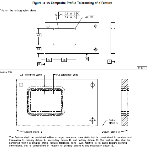
I know thats a lot to take in and a lot of words. This is where the standard is helpful. See below for an example of what I mean, note how the lower segment essentially floats within the upper segment.

11-25_unuwye.png
 
Chez,

Thanks for all that. You may have gotten me much closer. I understand the floating aspect. My goal is to be able to create a visual example of some dashed lines showing the simple upper tol zone callout. Then a few examples of differently rotated dashed lines with the tighter tolerance.

Before I do that, I understand the floating aspect with only the ability to rotate. My issue is that this ABC 3-2-1 rule is beat into my head. The bottom datum A removes 2 rotations and 1 translation then B removes the last translation. So give they are both in the drf in the lower I wondering how it can rotation and if it can is there a difference if it was datumless?

Thanks.
 
Before I do that, I understand the floating aspect with only the ability to rotate.

Actually its exactly the opposite of this - note I said it does not constrain translation, it only constrains rotation. Meaning in the lower frames/FRTZF of a composite tolerance only rotational DOF are allowed to be constrained. Meaning the tolerance zone defined by the lower frame 0.1 to |A|B| is allowed to translate in any direction [x,y,z] and NOT allowed to rotate in [u,v] relative to A and [w] relative to B.

Sorry if that wasn't clearer! My previous post was very verbose, it may have gotten lost in the body of that a bit.

My issue is that this ABC 3-2-1 rule is beat into my head.

Hopefully the above makes it all a bit clearer, and removes some of this confusion - however I just wanted to note, that the lower frame(s) of a composite tolerance (FRTZF) are a special case. Even if a datum feature can constrain one or more translational DOF, it won't just because that is the rules dictated by a composite tolerance. In this respect it is similar to, but not exactly the same, as a customized DRF. If this behavior is not desired, multiple single segment should be utilized.
 

Chez,

I'm just not understanding this composite shit.....I'm so sorry. You've put a lot of time into helping me.....and I'm and idiot. Let me view this shit over the week and I'll come back.
 
I think you need to know the "why." I mentioned in another thread that "why" isn't in the standard.

In this case:
The top level of the composite tolerance controls the location and orientation.

But what if you don't care about the location and orientation as much but want the mating part fit tightly? It's possible you would create the lower entry of the composite with no datum references and a very small tolerance.

But what if you don't care about the location and the only orientation you care about is that it's perpendicular to the mating surface? You create the composite with a reference to the mating surface, duplicating the same primary entry in the upper frame. For example - a d-hole cutout to capture a connector. It cannot turn too far, the first line stops most of that.

But what if you don't care so much about the location and you care about the orientation = like a cutout for an item in a dashboard where the user won't notice if it's off location by a little bit but easily see that it's crooked. Then you duplicate the primary and secondary references. Keep in mind neither one controls location - that's the job of the top entry. The lower entry only controls the orientation relative to the mentioned datum features.

So, why you chose these depends on what you want to get done.
 
sendithard,

Its totally fine! I hope nothing in my responses came across as frustrated or anything as that's absolutely not the case - I apologize if I'm not explaining myself well enough, that could be part of the disconnect. Regardless this is what I come here for - to discuss GD&T and related drawing/drafting topics in depth and I enjoy it.

Don't be too hard on yourself, these things don't always come easy and thats okay. I'm not going to pretend like I understood it the minute I picked it up, or if I'm being honest that I still fully do, theres plenty of things that regularly test my understanding - I'm always learning, we all are really. Just keep at it, you'll get it with perseverance. Feel free to ask questions as they come up, I mean it. In the meantime I'm going to work on a better way to explain the concept, perhaps with some better graphics. Keep on keeping on!
 
chez,

I took a needed break from GDT and I'm back now. You've been awesome thanks so much.... I'm also neck deep in learning pcdmis and my brain is absolutely fried. I'm understanding most of the GDT I see but composite profile and my next question will be MMB unless I get that through some sort of brain damage reading shit. Anyway, I believe I may understand the composite stuff finally. I'll be back after I wake up from these cocktails to explain myself more fully and see if I'm still lost or if I've been found. As, always thanks so much.

 
Chez/3D,

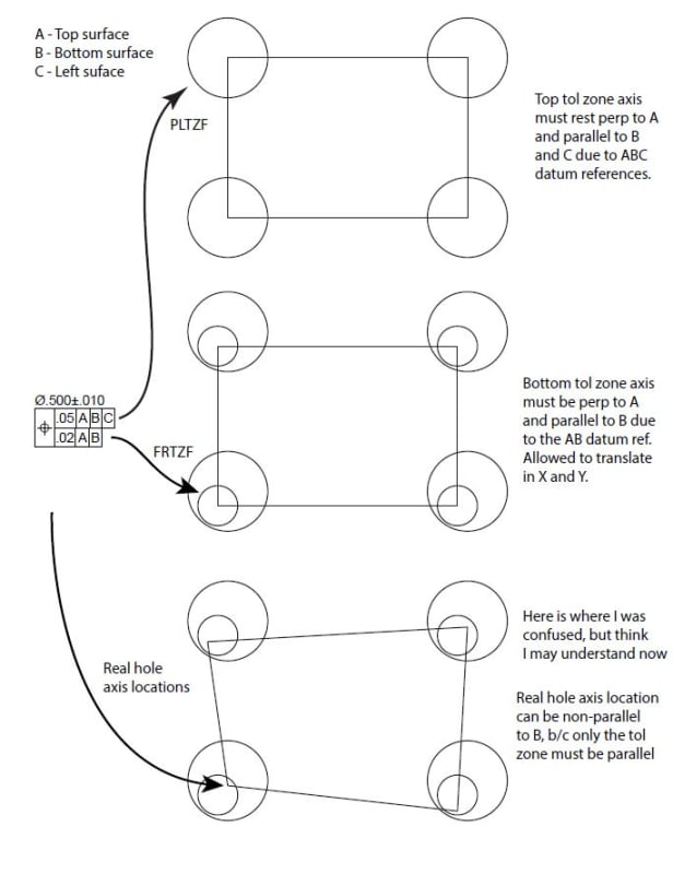
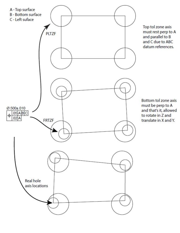
I'd like to share with you what I came up with and see if I am thinking right now. When I began visualizing this using positional tolerance instead of profile of a surface it began making more sense.

What I'm showing below is probably obvious, but the larger circle is just the top tolerance and the lower tolerance is resting inside it. The datum references dictate the translation and/or rotation that can take place of the tolerance zone inside the larger tol zone.

If AB is used in the lower, I believe you can no longer rotate in Z, but can still translate the 2nd zone in X and Y. Then if only A is used you get the additional rotation in Z.

I get confused as to what happens in this 2d view when there is no datum. Since you just remove perpendicularity to A how does this affect this zone and top view that we are witnessing?

Thanks again....here are my diagrams below....

AB_ddbw7v.jpg

---
A_zgu2pn.jpg

---
nodatum_urjg3f.jpg
 
The holes don't need to go straight in without a reference to A. They can all be at a steep angle, depending on material thickness.
 
Your question answered itself, in a sense: "I get confused as to what happens in this 2d view when there is no datum."

Expand from 2-D thinking to 3-D thinking...If you add a different view (side view, for instance), then try to visualize how the small zone could rotate relative to datum A, since the lower portion would no longer be referencing datum A.
In other words, the holes could be drilled at an angle (still within the perpendicularity allowance of .05) yet be perfectly oriented to one another.
 
Thanks, I think I understand composite tol zones much better now.

My last question relates to measuring a composite tolerance zone. Without a cmm I see this being a challenging task to do properly. I'd guess composite profile of a surface would be much harder than positional. There seems to be so many variations the measurements by hand could get confusing. Thinking from an engineer standpoint creating the tolerances for the composite profile of a surface seems difficult to get right without over tightening all the tols.

Are composite tolerances difficult to measure without a cmm?
 
For a 2D projection, typically one would create a precise template that matches the least material border and then use a feeler gage or feeler wires of some type to see if the gap exceeds the zone width. The simplification is you don't measure the profile, you measure the deviation from the desired profile or one of the profile limits.

For thin items an optical comparator is used where the gage is a transparency with the profile limits marked on it.
 
To clarify - least material border for the gage, maximum material border for the part.
 
Status
Not open for further replies.

Part and Inventory Search

Sponsor