Continue to Site

Eng-Tips is the largest engineering community on the Internet

Intelligent Work Forums for Engineering Professionals

  • Congratulations IDS on being selected by the Eng-Tips community for having the most helpful posts in the forums last week. Way to Go!

Irregular pattern as a datum. How to define DRF origin??? 2

Status
Not open for further replies.

JesseLou

Mechanical
Aug 15, 2023
3
Hey all,

I can't find much information on this at all.... Even in the ASME standard.. Only a couple pages on patterns as datums.


So... I have a irregular pattern that I am picking up the top of to make Datum-D and then I want to make the pattern itself Datum-E so we can check a few holes relative to this pattern...

Question1: If there was not DRF(datum reference frame) origin called out, where would it be for Datum-E, the 7x bolt pattern?

Question2: What would be the best way to locate it?

Could I put it wherever I want and just draw some basic dimensions from the red centerline ( which I manually made)??
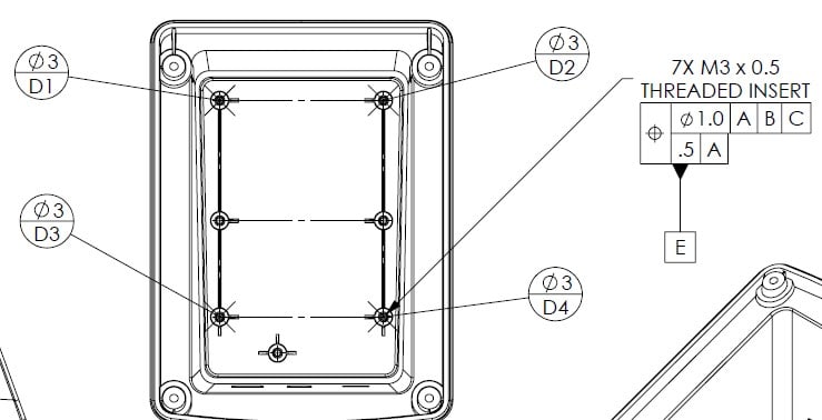
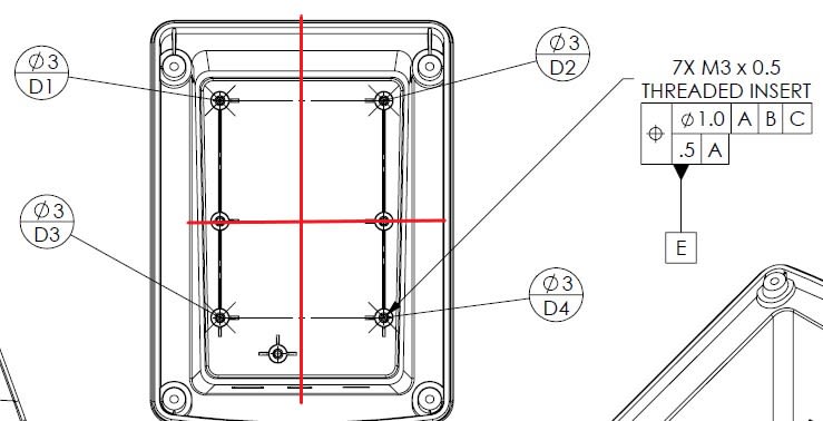
datum-E_vqr5z0.jpg

datum-E_-_Copy_nxtnnk.jpg
 
Replies continue below

Recommended for you

That helped.... some.. I still am not clear for inspection purposes.

I am still not clear. When picking up datum-E on the CMM... I will pick up all 7 holes... then:
1. How or where do I tell the CMM software where the DRF origin is for Datum-E (locking 2 DOF)
2. How do I clock the pattern (last DOF)

Thanks in advance.


profile_gwuu55.jpg
 
The CMM software needs to be smart enough to figure that out all by itself. Any origin will work as it will be a constant value offset that is added/subtracted between the datum reference frame and the feature relating frame.

Orientation is trickier as the standard Pontius Pilate method is to suggest simultaneously expanding features will magically orient the part. Having produced that explanation, their hands are clean.

Practically, I would treat it as if the threads are called out MMC with zero size variation and use threaded gauge pins. CMM software should handle the MMC case. Whatever solution to orientation the CMM generates for that pattern is retained for the use as a datum feature.

For example: (not affiliated - check other suppliers as well)
---

The little that is shown is like a Jenga tower of tolerance instability.

Are the 3mm diameter datum targets on top of the 3 mm diameter threaded holes?

Do 4 points define a plane?

Is 0.5 mm out of perpendicularity to whatever A is being added to whatever allowed parallelism of D going to allow the mating screws to fit the mating part they project through?

The good news is whoever makes the part will likely make it far more precisely than you have allowed variation limits to. You could probable double the tolerance values and the maker would not change a thing. But it will be a bad day if you get someone who is careless and makes what you allow.
 
JesseLou said:
1. How or where do I tell the CMM software where the DRF origin is for Datum-E (locking 2 DOF)
2. How do I clock the pattern (last DOF)

The primary datum feature D (formed by D1/D2/D3 and D4) constrained 3 DOFs (Z, u, v), and the secondary datum feature E (the 7 threaded inserts hole pattern) constrained the 3 remaining DOFs (X, Y, w), since the secondary datum feature will restricts the part movemment in three directions, it serves as both a secondary and tertiary datum feature, so tertiary datum feature is not required.

Please note that when a hole pattern is used as datum feature, it is almost always referenced at MMC, will recommend your FCF callout to add the material mofifier as shown.
2023-08-15_134418_leakzx.jpg


Based on the above reason of material modifier added on the FCF, the datum feature simulator will be a pattern of virtual condition gage pins, therefore a datum axis exists at the center of each virtual condition gage pin. Since the page pins are considered to be theoretically perfect, measurements can be taken from any one of the 7 datum axes.

From what I understand on your post, it seems you missed diameter symbol in ftont of 0.5 tol on the lower segment of the composite position callout, it seems you also missed "all around" symbol on the profile callout as well.

Season
 
3DDave said:
The little that is shown is like a Jenga tower of tolerance instability.

Are the 3mm diameter datum targets on top of the 3 mm diameter threaded holes?

Do 4 points define a plane?

Is 0.5 mm out of perpendicularity to whatever A is being added to whatever allowed parallelism of D going to allow the mating screws to fit the mating part they project through?

The good news is whoever makes the part will likely make it far more precisely than you have allowed variation limits to. You could probable double the tolerance values and the maker would not change a thing. But it will be a bad day if you get someone who is careless and makes what you allow.

Yes. I know the tolerancing looks thin. I'm trying to help out the engineering dept with their drawings. They have quite a few greenhorn engineers and they say that they had hardly any GD&T and print drafting training. These were some initial ideas I came up with. My actual job is machining and inspection but they are pulling me in to help them out.

Yes the 4 points are the top of the boss' with the threaded inserts to establish a plane there. A PCB sits there. With those 4 datum targets making datum-D, where/how would be the best place to callout parallelism to Datum-A, for D?

Good point on the perpendicularity for the threaded inserts. It should be fine since it just short screws that hold down the PCB. We're trying to make it as pass-able as possible. The most important thing is the PCBs position to the I/O slots in the back that is called out with profile. The connectors have to line up with the holes slots well. Most of the other feature locations are pretty loose.
 
With a 5mm long screw that has a 5mm diameter head, the perpendicularity allows one side of the screw head to be 0.5mm above the mating surface. The actual perpendicularity should be a maximum of 0.1, which will leave a mark.

A profile tolerance to control the tops of the standoffs is typical. I would use two near the openings and only one away to define a plane and set the target to be the entire top surface of the standoffs. If you have had a table that rocks back and forth because one of the four feet don't touch then you have seen that four points aren't suitable to define a plane. Keep the profile tolerance to the acceptable twist the board can handle.
 
Status
Not open for further replies.

Part and Inventory Search

Sponsor