Continue to Site

Eng-Tips is the largest engineering community on the Internet

Intelligent Work Forums for Engineering Professionals

  • Congratulations KootK on being selected by the Eng-Tips community for having the most helpful posts in the forums last week. Way to Go!

Is time delay required when switching from LO to HI speed on 3 phase, two winding motor? 2

Status
Not open for further replies.

generatorlabs

Industrial
May 21, 2016
7
Working on replacing a starter on an abandoned warehouse. The starter is basically destroyed and missing major parts.
The motor is a 5 hp, two winding, 3 phase motor, running at 480. The starter will be reversible. The motor is being rewound.
I have not worked on a separate winding motor before however I have full drawings for the original starter.
The drawings are from the 1950's. They are a little sparse.

My question is:
a) When going from LO to HI speed, should a delay timer be inserted between the LO speed and HI speed contactors with this motor design? If so what delay time?
b) I see that the LO speed winding should be shunted when running at HI speed. Why is it shunted if the windings are separate? Is that to quelch induced currents?
c) I am assuming I will just use another contactor for shunting. Does the shunting contactor require the same specs as the Lo, Hi, Forward & Reverse contactors?

Just for FYI, I am using ABB contactors. They are IEC frame. I have chosen IEC frames sizes equivalent to NEMA1 contactors. All mechanical/electrical contactor interlocks will be in place.

Any advice appreciated!
 
Replies continue below

Recommended for you

Can you scan (or photograph?) the original drawings and post them? The 'shunt' contactor sounds awfully like the star point contactor of the controlgear for a Dahlander motor.

The delay needs to be long enough to allow the contactors to mechanically drop out before trying to energise the other set, and to allow any induced voltage from the motor to die away to prevent large switching transients which can trip breakers or blow fuselinks. On a small motor this will be a short period - perhaps less than one second - but there should definitely be a delay.
 
I agree with ScottyUK, the presence of a 3rd contactor would it be something I have ever seen for a 2S2W motor starter. It's more likely a 2S1W Consequent Pole motor starter (what he referred to as a "Dahlander" starter, a term we don't use here). So if it is a 2S1W starter, then assuming you read from the motor nameplate that it is a 2S2W motor the question is, was someone trying to use it on that motor? That might explain why it has been gutted, because someone was constantly replacing parts not understanding the true nature of the problems

Oh and yes, he's right about the time delay, it needs to be there. 1 second should be fine, but people often set it for the measured coast down time for the load to go from high to low, which varies based on the load inertia. It's not really necessary, just common practice.


"You measure the size of the accomplishment by the obstacles you had to overcome to reach your goals" -- Booker T. Washington
 
Shunting or shorting the leads on a two winding motor sounds like a really bad idea. Like Jeff, I have never seen it yet. But I haven't seen everything yet.
I have seen quite a few two speed motors jump from low speed to high speed without a delay.
Generally the interlock contacts ensure that one contactor has dropped out before the other contactor is energized. Hopefully the windings and switching will be arranged so that the motor will tend to accelerate rather than experience a transient de-cceleration as the motor jumps to high speed. A time delay going from high speed is common. Give the motor time to coast down before energizing low speed. The time is greatly dependant on the inertia of the load.

Bill
--------------------
"Why not the best?"
Jimmy Carter
 
Thank you all for your replies.

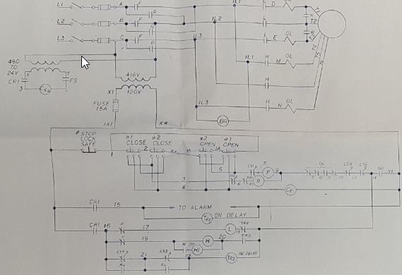
I have attached a photo. Please help me validate if what I am reading on the prints is correct. Is that a shunting contactor? What function is it performing?
I see there is a consensus on inserting a short delay to allow circuits to stabilize.

From what I gather there were 2 timers in the original plans. The first delay was to allow klaxons to sound prior to motor movement. This also prevented motor plugging.
The second was there to allow LO to get ramped up and then switch to HI.
This was done with large ugly pneumatic timers, which of course have completely deteriorated since the 1950's.
The timing sequence was a one-way operation. There was no decel. It was just an abrupt stop.
I think the contactors just clacked between LO and HI with no short interval in-between, kind of brute force style and possibly producing some nifty arcing. There was mechanical interlocks between contactors.
I also imagine that is why these contactors were so large for their application.
I was thinking there should be at least 60ms delay module in there, like you would typically see on WYE DELTA starters sold by ABB and others. Since this motor style is foreign to me I figured I would reach out to you fine folks.
I guess they did not have the tech for short span timers back then unless they used tube technology because transistors were fantasy items in the early 50's

Below you can see there were some old style thermal OVL breakers on the drawing. You can also see N.O. contactors laid across T1, T2 & T3. The motor plate shows that terms should be shorted as well.
Based on what I am looking at this is a pure two winding motor. I just can't really understand why T1, T2 & T3 need to be shorted.

This was probably state of the art when it first came out. There are some things about this that make me cringe a little. The motors are surprisingly over engineered and in good shape. They are getting rewound.
The human control surfaces are less than 5 ft from the motor and are metal, within metal casings and all of the switches are carrying 120VAC control voltages. Even though the case should be grounded, that is where I think I am going to deviate from the plans and do 24VAC control voltages. These are operated in potentially wet conditions and well, what can I say, it just leaves me with a bad feeling. It is going to be nice to see them come back to life, kinda like reviving an old roller coaster :)
Just in case you are wondering, the customer wants it to follow the original plans. VFD might work but with these motors I could not be certain. They say if it worked in the 50's, it will work now.


little_yxqwia.jpg


MotorPlate1_Medium_qawha9.jpg
 
Yes, that's definitely the shorting contactor for a Dahlander connection. Normally contactor 'H1' closes slightly ahead of contactor 'H' to put the shorting link in just before the winding is energised, although this design seems to close the shorting link after the winding is energised.

There's a reversing arrangement at the left side (contactors 'F' and 'R'), and what looks like a brake coil 'BR' hung across 1L1 - 1L3.
 
Sir. Probably it is a Dahlander connection. I think this name is not frequently used in US. Anyway this two-speed with commutating pole windings is the most used AC motor 2 speed system.Speed ratio is 2:1.It can be connected as "Constant Torque":torque is constant on both speeds, power ratio is 0,63:1, D/YY connected. "Constant Power":Torque ratio 2:1, HP remains constant. YY/D connected. "Variable Torque": Power ratio 1:4. Y/YY connected, applied for fans, pumps. Centrifugal load recommends an idle time when selecting from High speed to Low speed (HP ratio is 4!). Two separated OL protection devices shall be provided. The shorting contactor shall be closed always in advance. I hope it helps.
 
@ electrolitic "The shorting contactor shall be closed always in advance"

Should I still insert a short timer between when Lo Speed contactor releases and Hi Speed shorting contactors pull in?
Even though there are interlocks preventing both from occurring at the same time I was just wondering if there is a best practice to add an additional very short delay.
Below describes what I am seeing:

Request movement---->Sounder for 2 seconds---->Lo Speed Contactor ON----->2 second delay----->Lo Speed Contactor OFF----(should there be a short delay be here?)----->Hi Speed Shunt Contactor ON------>Hi Speed Contactor ON
 
Many designs did not use a delay between low speed and high speed. Depending on the application a delay nay be counterproductive. The interlocking contacts will prevent the contactors from overlapping.

Bill
--------------------
"Why not the best?"
Jimmy Carter
 
Sirs. I wrote time delay between high speed and low speed (only at this order) considering Dahlander "Variable Torque" connection and centrifugal loads as fans, pumps (an eventual high inertia and the power ratio 4/1). Please see diagrams-winding, at Google. It is a typical circuit.
To see also: Electric operating principles and circuits-Thomas Feick-Bad Hersfeld. There, the recommendation of shorting contactor to be closed in advance and also the motor internal connection. The Fwd/Rev selection shall consider the available torque, the load, time to normal stop or mech brake or plugging, etc. No other time relays are necessary. Hope it helps.
 
Itsmoked. Sorry, really doesn't work. Please try : circuit diagrams 2 speed, 1 winding:2 speed.

It is a typical Dahlander diagram from ABB. Sorry again.
 
Thank you all for your very informative replies.
I think I can proceed safely with my automation project now that I have some solid images I can reference.
I tried to explain this to my industrial rep at Galco and he was baffled by it.
I then pointed them to an image of the Dahlander motor configuration and they had the "oooh, that's nioe" moment.

Thanks for all of your input. It is greatly appreciated.
 
Status
Not open for further replies.

Part and Inventory Search

Sponsor