Good morning! ![[wavey2]](/data/assets/smilies/wavey2.gif "[wavey2] [wavey2]")
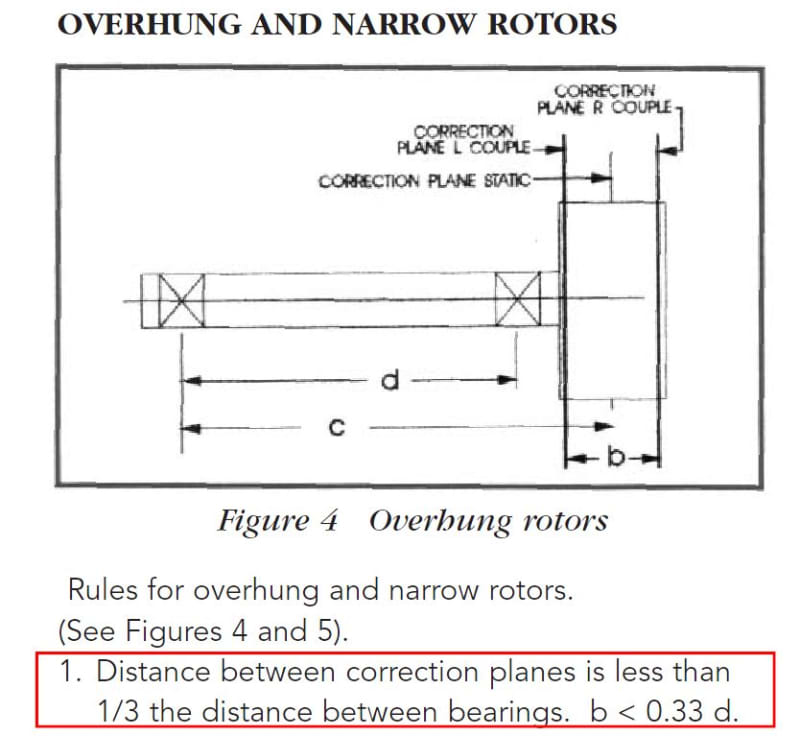
I am reviewing an existing rotor design where Dim b is 0.65" and Dim d is 0.4" (see picture below). The distance clearly violates ISO 1940/1 - Balance Requirements for Rotors (link to doc which references ISO 1940/1). My questions are:
[ol 1]
[li]Since distance d is so small I believe it is amplifying the imbalance. Currently the rotor is balanced as if it was supported on both sides (not cantilevered). Do I need to switch to a cantilevered balancing machine setup? Or do you know a way to calculate how much I need to lower my balance requirements to compensate for the distance between the bearing planes.[/li]
[li]The distance between the bearings is so small because they are side by side, with only a very small shim between them. However, on the opposite side of the cantilevered rotor there is a spline shaft which couples with a shaft from a gearbox. Obviously the gearbox shaft has its own set of bearings, do they somehow factor into the value of b]Dim d[/b]?[/li]
[/ol]
I have very little experience with balancing so your help is greatly appreciated. Thanks!![[tiphat]](/data/assets/smilies/tiphat.gif "[tiphat] [tiphat]")
I am reviewing an existing rotor design where Dim b is 0.65" and Dim d is 0.4" (see picture below). The distance clearly violates ISO 1940/1 - Balance Requirements for Rotors (link to doc which references ISO 1940/1). My questions are:
[ol 1]
[li]Since distance d is so small I believe it is amplifying the imbalance. Currently the rotor is balanced as if it was supported on both sides (not cantilevered). Do I need to switch to a cantilevered balancing machine setup? Or do you know a way to calculate how much I need to lower my balance requirements to compensate for the distance between the bearing planes.[/li]
[li]The distance between the bearings is so small because they are side by side, with only a very small shim between them. However, on the opposite side of the cantilevered rotor there is a spline shaft which couples with a shaft from a gearbox. Obviously the gearbox shaft has its own set of bearings, do they somehow factor into the value of b]Dim d[/b]?[/li]
[/ol]
I have very little experience with balancing so your help is greatly appreciated. Thanks!