Continue to Site

Eng-Tips is the largest engineering community on the Internet

Intelligent Work Forums for Engineering Professionals

  • Congratulations KootK on being selected by the Eng-Tips community for having the most helpful posts in the forums last week. Way to Go!

Vehicle Anti-lock brake rotor system, increase horsepower, Brake Rotor takes 175 ft-lbs, 36 Hp to spin up, really? free wheeling the brake rotor

kaazx9r

Mechanical
Jul 27, 2022
34
Hello, I wanted to see if it would be possible to create an anti-lock brake rotor that would unlock on non-braking events to free up the power it takes to spin them to speed.

But my numbers seem pretty high. My calculation

Taking a typical Shelby GT500 brake rotor(I know you all have these laying around like me), consider this brake Rotor laying flat on your screen, where z-axis is coming out of the screen, and rotating, with an outer radius is 7.5”, inner radius is 4.5”, thickness is 1.25” and mass of 31.4 lbs, what is the inertia? Then find the torque and horsepower to accelerate the brake rotor to a target rotational speed of 700 rpm to 1500 rpm in 4 seconds about its z-axis. (Basically a tire diameter of 28.5" to get wheel rpm from 60mph to 130mph, gives 700rpm to 1500rpm wheel/rotor speed.
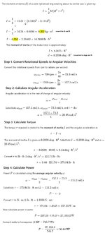
initial_calculations.jpg

So as the title states I got 175 ft-lb and 36Hp. But torque acting on the hub given a 3.55 rear diff gear ratio, we'll get 49ft-lb and 10.14 Hp is what the engine needs if you go through a 1:1 4th gear ratio. Multiply this by 4 wheels (say rear wheels have 75% smaller brake rotors), you're looking at 172 ft-lb and 35Hp from the engine just to turn the brake rotors. Seems reasonable?

So what kind of system would disengage, Chatgpt solutions:
1. Sprag or Overrunning Clutch
A sprag or overrunning clutch allows torque transmission in only one direction. When braking force is applied, it locks the rotor to the hub, but when no braking force is applied, it allows the rotor to spin freely.

2. Pneumatic or Hydraulic Actuator with a Locking Pin
3. Mechanical Locking Hub (Manually or Automatically Controlled)
4. Electromechanical Braking System (e.g., Electric Park Brake Actuator)
5. Electromagnetic Clutch
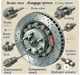
anti_lock_brake_rotor.jpg

Chatgpt creates some strange images but anyway, the system would have to be normally closed for safety. And the added weight is another thing to consider. You need to engage it a split millisecond before the braking event but that should be doable or you can gradually bring the freewheeling rotor to match the hub speed where it would take a lot less torque over the greater time.

I think a synchro dog teeth transmission style system would also work but may not be normally closed. And spinning it up to speed to match the hub speed would have to start before the braking event but on a straight away this is not an issue due to the extra time, but still creates more load on the vehicle. You want the rotor freewheeling when accelerating to save that horsepower and enough to take over another vehicle, once at cruising speed, the system would start to match the rotor and wheel/hub speed.

Kindly discuss.

Edit to add cleaner calculations.
 
Last edited:
Replies continue below

Recommended for you

You are though taking very conservative data.

The brake disc at 32 lbs seems right for this monster of a car, but that is total weight of the disc including the hub. The inner hub hole is 70mm diam or 1.4" radius.

I looked up the acceleration times and from 60 to 130 it takes 8 seconds. So pretty startling alright, but not 4 seconds.

Try plugging those numbers in and see what happens?
Most of the weight on between 4.5" and 7.5" radius, the hub part only weighs 2 lbs.
 
Most. So reduce the weight you use and 2lb didn't seem right.

So use this dimensions but maybe 26 or 28 lbs. And acceleration is half.
 
I'm not sure if you're getting what I wrote, the system disengages and engages, so there is no moving backwards because rotor is fully locked with the wheel hub when the system engages. I'm talking about non braking events. It better be locked when you brake(reason you want it normally closed), otherwise it would act as you have stated.
I did miss you are proposing the rotor system is normally closed. So this will not provide a reduction of rotation of the wheels from a stationary condition and only disengage/engage as a momentary 'horsepower boost'?
 
Most. So reduce the weight you use and 2lb didn't seem right.

So use this dimensions but maybe 26 or 28 lbs. And acceleration is half.
Respectively no thanks. I'm going to stick to my numbers so we can all stay on the same page and get the right calculation.

Going back to Gregs calculation, using all metric and mass units,
"T=21*.6=12 Nm
Hence power is 115*12 W, about 1.5 kW, or 2 hp"

It takes 2Hp, to rotate a brake rotor with a weight of almost 32 pounds, from 700rpm to 1500rpm in 4 seconds? how can we test this? I feel its a bit low. I keep using weight and you all keep using mass. So lets try to clear this up please.
 
I did miss you are proposing the rotor system is normally closed. So this will not provide a reduction of rotation of the wheels from a stationary condition and only disengage/engage as a momentary 'horsepower boost'?
Correct. I think even 0-60mph(0 rpm to 700 wheel rpm), if you don't need the brake, and the brake rotor is free wheeling, I think it will free up some horsepower.
 
kaazx9r,

I am confused. Brakes use friction to convert your kinetic energy into heat. Anti-lock brakes prevent locked brakes by applying and releasing them rapidly. Back in the day, we were taught to pump the brakes. In a non-braking event, you are not braking, and anti-lock does not, or at least, should not do anything.

If you have an electric car, i.e., not a Shelby GT500, you can use your motors to convert kinetic energy back into electric energy, re-energising your batteries. I am not an expert, but my gut feeling is that an electric motor acting as a generator, will not lock your tires. The anti-locking does not kick in until your friction brakes do.

Also, while I acknowledge that your spinning brake rotors have kinetic energy, this must be way less than the kinetic energy of your whole car. Shelby GT500s are not particularly light, and neither are electric cars with or without regnerative braking.

Power equals force times velocity. A horsepower is 33000ft.lb/min. Let's decelerate a 3500lb car from 130mph at 1G.

At 1G deceleration, F=3500lb.

Power = Fv = 3500lb X 130mile/hr x 5280ft/mile x 1/60hr/min = 40,000,000ft.lb/min

Power = 40,000,000ft.lb/min/33000HP.min/ft.lb = 1200HP.

I suppose that the rotational inertia of your brakes, and drive train back to your clutch, will add to that, but not much. This power drops along with your speed. This all is kinetic energy converted to heat.
 
What Chatgpt drew up looks just like an electric motor with some screws going every which way that I said it was strange but it’s just an illustration, the actual modes Chatgpt came up with is written after the illustration.

Getting back to the system and calculations, yes you can use the system as an anti lock braking system, what I should of said was on braking events, you can pulse the system on and off to disengage the wheel, same as what any abs does just in a different way.

Technically you could use it as a traction control as well. If the rotor is free wheeling on acceleration but the wheel is starting to spin and lose traction, you could pulse the system to slow the wheel down, since the force needed to spin up a non moving rotor would slow down the entire wheel, it acts as a brake momentarily and regain traction. Could even apply pressure on the brakes and let the system engage the rotor on and off.

But I want to see the calculations first.
 
NO. The rotational inertia of the disc is the same on Earth as it is on the moon.
 
NO. The rotational inertia of the disc is the same on Earth as it is on the moon.
I’m okay on the inertia being the same any place but the force or in my case the torque and horsepower required to accelerate the 30 some pound rotor disc from 700rpm to 1500rpm in 4 seconds is about 2Hp?
 
Regardless of whether the rotors are spinning or free-wheeling, they still need to accelerate/decelerate, just like any other component of the vehicle. F=ma/gc (imperial units) and Power = F x velocity - have you looked at what power is required to linearly accelerate that load?
 
Hello, I wanted to see if it would be possible to create an anti-lock brake rotor that would unlock on non-braking events to free up the power it takes to spin them to speed.

Yes. it would be possible.

It's also not worth doing.

If kaazx9r wishes to spend the money developing it, go for it. I am not sure ChatGPT will be able to do the detailed design, but give that a try as well.

Also, it is poor form to go and edit any posts to change what they say after others have made responses. Fix a typo? Sure. Correct punctuation? OK.

Drop out some biasing statements that people looked at and responded to?
 
Regardless of whether the rotors are spinning or free-wheeling, they still need to accelerate/decelerate, just like any other component of the vehicle. F=ma/gc (imperial units) and Power = F x velocity - have you looked at what power is required to linearly accelerate that load?
I'm just changing when i want to do the accelerating and decelerating and over a different period of time. Linearly doesn't matter because the vehicle has to carry that load no matter what, i'm asking for the calculation of what the engine needs to turn that brake rotor.
 
Yes. it would be possible.

It's also not worth doing.

If kaazx9r wishes to spend the money developing it, go for it. I am not sure ChatGPT will be able to do the detailed design, but give that a try as well.

Also, it is poor form to go and edit any posts to change what they say after others have made responses. Fix a typo? Sure. Correct punctuation? OK.

Drop out some biasing statements that people looked at and responded to? That's being a jerk.
I'll try not to do that, just didn't want repeat questions from the initial post, i'll put the edits in the footnotes. Can you help on the calculation, Greg got around 2Hp, I got around 30 Hp.
 
You don't need a calculation, having already decided to do this thing.

The clue to proceed is whether any of the 10's of thousands of other people doing similar work already produced this and put it into racing cars.

They have the time, the money, the expertise, the facilities, and the motivation to shave tiny amounts of time.

Overall the calculations don't matter because the fundamental concept isn't useful. You won't believe it until you build one, so start there.
No one has decided anything, do you agree with any of the torque and horsepower answers? No need to dodge around question by saying what is useful or what has been done or not been done. Everyone already gets that.

I’m asking a question regarding torque and horsepower based on the weight and times given.
 
This seems more reasonable, thank you. Should you use gravity acceleration when doing metric? which would be .6 kg/m^2 x 9.81 m/s^2, which gets you to 5.8 N/m^2 multiply this by acceleration 21 rad/sec gets you 123.6 Nm or 90 ft-lb.

When doing calculations in proper SI units, "g" has no business anywhere unless the force of gravity is actually involved in whatever you are interested in, which is not the case here.
 
I’m okay on the inertia being the same any place but the force or in my case the torque and horsepower required to accelerate the 30 some pound rotor disc from 700rpm to 1500rpm in 4 seconds is about 2Hp?

By gut feel this sounds about right.

Just out of curiosity ... Steel disk 400mm diameter and 20mm thick has a volume of 2513 cm3 and at 7.8 g/cm3 density of steel, that's about 19 kg, and considering that those dimensions are ruff approximations and I know the centre of the disk isn't full thickness, your brake rotor mass would be in the ballpark. I guess it didn't sound right to me, because I've never owned a vehicle which had brake rotors even remotely close to that size.
I appreciate that, I will figure out a way to test it. My thoughts are a 3hp motor, and just mount the brake rotor to the shaft and turn it on and measure the time and final rpm. I don’t have to match my speed of 1500 rpm since I can just use the formula that was written. The correct one.
 

Part and Inventory Search

Sponsor