Eng-Tips is the largest engineering community on the Internet

Intelligent Work Forums for Engineering Professionals

ISO - Flatness CZ of Offset Features

Status
Not open for further replies.

Mech1595

Mechanical
Oct 16, 2023
29
0
1
US
Hello All,

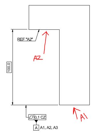
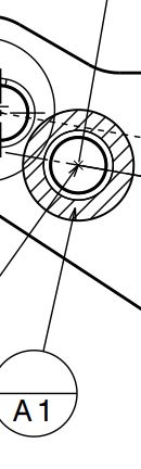
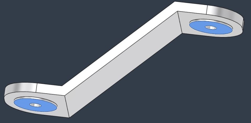
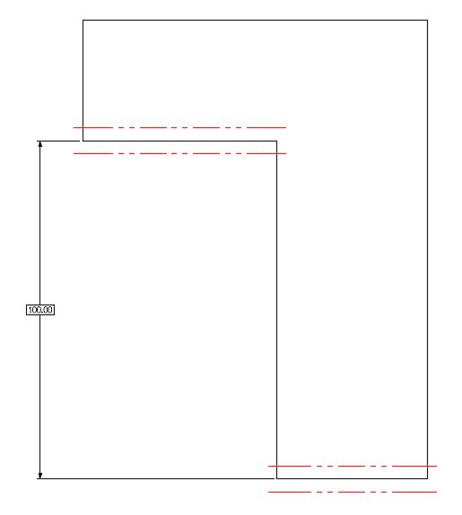
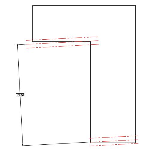
I received a customer print for review with the following callout for [Flatness | 0.1 CZ] for the two identified surfaces. I created an example with a simplified model below, but kept all of the notes/callouts/etc. the same as the customer print.

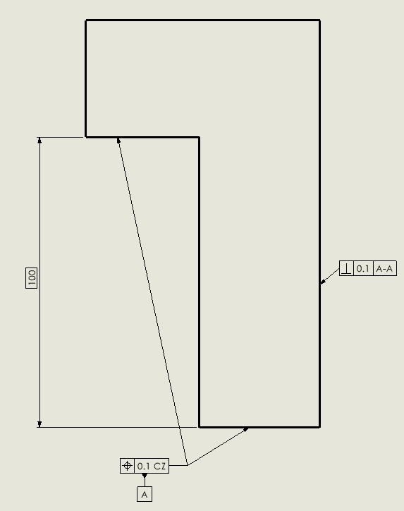
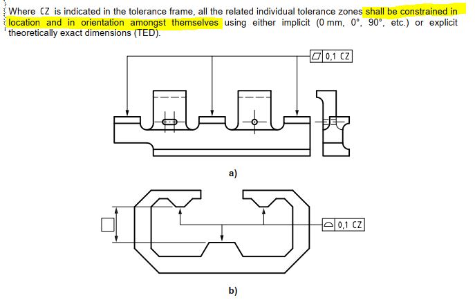
My experience is limited with ISO GPS, but I understand the concept of CZ when applied to co-planar surfaces (as shown in the second image). I'm just a little confused on what the tolerance zone will look like in this example, with the two offset surfaces. Is this still just a form control? Do I treat it as two separate (but parallel) tolerance zones, and ignore the basic offset?


ISO_CZ_Example_fpbn9p.jpg


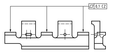
Second image pulled from ISO 1101 for reference
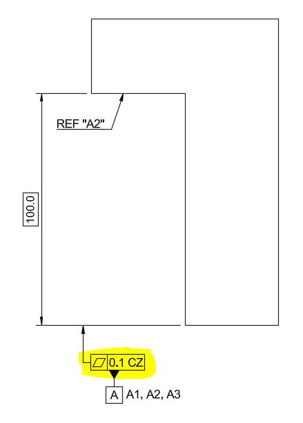
ISO_GPS_ldlr7l.jpg
 
Replies continue below

Recommended for you

Hi, Mech1595:

What are "A1" and "A3"? Are there 3 separated surface features? I don't understand why the feature control frame is attached to an extension line of the dimension 100.0 BASIC.

Best regards,

Alex
 
Hi Alex,

There's two separate surfaces for A1 & A2 (as shown below, identified via datum targets in other views), and A3....doesn't exist! Already noted on my design review, but I wanted to make sure the example showed the exact same info. Unfortunately I can't share the actual print per the NDA.

Datum_A_gqskug.jpg
 
Hi, Mech1595:

The print has an issue since "A3" does not exist. Are these "A1" and "A2" datum target points, lines, or areas? They look like multiple datums. How is datum A used?

I am not very familiar with ISO 1101. To me, your customer wants to achieve something like this one below (ASME Y14.5).

Best regards,

Alex
 
 https://files.engineering.com/getfile.aspx?folder=4a79bd65-51d5-419f-8989-409fa0930375&file=Planar_multiple_datum.PNG
If they are offset horizontally as little as depicted it can end up with only one of the two surfaces making contact with the inspection fixture or CMM software defined inspection fixture.
 
3DDave,

Thanks for the info. That's how I was leaning initially, but wanted to first check if this was a valid use-case that I just wasn't familiar with. This isn't the only issue with the drawing, so I won't be surprised if this is just an incorrect application of GD&T.


Alex,

A1 & A2 are specified using datum target areas. Here's a little more detailed example showing design intent (3DDave - Horizontal Offset is roughly 150mm in the actual model). A1 & A2 are defined as the contact pads around the fastener holes.

I agree with your example, the assembly condition is similar enough to the real part. I could understand using separate flatness or profile controls to qualify the offset datum features, but the addition of the CZ modifier is throwing me off.

Datum_Targets_wsilcl.jpg

Improved_Edample_oygeod.jpg
 
There's a few problems here. Firstly for a combined flatness tolerance zone, the nominal surfaces must be coplanar (See ISO 5458 section 1). Even if they used an applicable constraint such as position, the control is attached to the extension line of the bottom face and as such only applies to it. To apply to both surfaces, the second surface needs a FCF with a SIM modifier, or the FCF should have arrows which attach to both faces. In addition, datum targets are used to restrict which portions of a datum feature apply when referencing the datum; they have no affect on the flatness tolerance. Finally, datum target A2 can't be applied to the second face because it is a separate feature, not a restriction of datum A. They could be made into a common datum, but a datum target doesn't achieve that.

Here is an example of what I think the designer is looking to achieve. I added the perpendicularity callout to show something referencing the combined datum.
Capture_y5tphy.png
 
Ryan6338,

Just for my own education:
If the customer wanted to maintain datum targets to establish Datum A, could they change from Target Areas to Target Points, similar to the image below? (from Y14.5-2009 Fig 4-47)
Is the use of the Target Areas not valid (in their example) because they're effectively establishing two separate planes (as shown in Alex's example from Fig 4-22)? Am I understanding that correctly?


Figure_4-47_derace.jpg
 
Mech1595, the way I understand it, datum targets are only used when you want a portion of s surface or surfaces to be used for creating a datum. In Ryan's example, although there are 2 surfaces, they still want the full area of each surface to be contacted for deriving the datum (or as much surface area as possible).
 
Why are the datum B and C symbols applied to tangent lines that aren't part of the defining datum targets? The intention of datum targets is to ignore the underlying form of the surface as that surface shape is unreliable. In fact the note NOTE 1 indicates that with CF, datum B is established at the apex of the wedge, not on the part surface.

C1 and C2 are supposed to move synchronously - at the same time - and not symmetrically. Odd requirement.
 
CheckerHater,

Thanks for sharing, not sure how I completely missed that image the first time I looked in 1101.
So back to the OP example: Does this mean that it would create two parallel tolerance zones, separated by the basic [100]? Would the zones be allowed to "rotate" with respect to each other as shown in the last image, as long as the basic [100] and relative parallelism is maintained?


1101_Text_f8clow.jpg


Tol_Zone_jlyftr.jpg


Tol_Zone_Rotated_uxxm16.jpg
 
Since no datum is referenced, the frame will only control relations of features to each other.

It still looks like flatness may be not the best choice.

"For every expert there is an equal and opposite expert"
Arthur C. Clarke Profiles of the future

 
Hi,

Is this feature control frame below valid according to ISO 1101?

position | 0.1 | cz

According to ASME Y14.5-2018, this is invalid (ignore "cz") as position applies to feature of sizes only. These two surfaces are not feature of sizes.

Best regards,

Alex
 
Mech1595,

I agree with 3Ddave as it being a defect, incomplete drawing. Looking at your figure, first of all the flatness requirement is only valid for the lower surface. The CZ means nothing unless there is a "2 x" notation or multiple leaders pointing to other surfaces for the flatness requirement.

If datum targets are the intent (ISO 5459 7.4.2.4 rule 4), which is implied by the A1, A2, A3 notation, it is ambiguous because nowhere does it show the datum targets.

If Ref A in this case is intended as a common datum collected from each surface included in the common zone, the "Ref 2" does not make sense.

I agree with Ryan6338 regarding possible design intent.

 
Status
Not open for further replies.
Back
Top