Eng-Tips is the largest engineering community on the Internet

Intelligent Work Forums for Engineering Professionals

  • Congratulations waross on being selected by the Tek-Tips community for having the most helpful posts in the forums last week. Way to Go!

ISO GPS: Does parallelism to a common datum also control coaxiality?

Status
Not open for further replies.

Eurotex

Mechanical
Sep 14, 2020
11
0
0
US
CAUTION: This post uses the ISO GPS system of geometric dimensioning and tolerancing

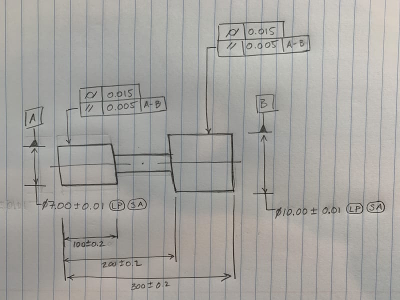
Can the parallelism tolerance shown in the below image (with respect to common datum A-B) be considered to control coaxiality of the A and B diameters? If so, would you assume the equivalent coaxiality/position tolerance to be 0.005?

IMG_0024_loahdf.jpg
 
Replies continue below

Recommended for you

"NO" would be my first thought also, but it does seem to control coaxiality to some degree. Can you think of why someone would use this form of control? Or how would you account for this form of control in a floating fastener scenario (where the above drawing details the fastener)?
 
Eurotex said:
But I'm not sure what the equivalent location/position tolerance would be. Any ideas?

Not sure I understand. Please advise.

Any functional tolerance value is acceptable and shown parallelism would be refinement.
 
This is a special case where the features are themselves used as the datum features against which the feature orientation is compared.
 
They should add this to the standard:

"An orientation tolerance does not control location of features even if it looks like it does"

"For every expert there is an equal and opposite expert"
Arthur C. Clarke Profiles of the future

 
The obvious outcome of this is that the parallelism being controlled can't be met without some level of coaxiality between the cylindrical datum features. Not sure it provides a requirement equivalent to position within 0.005 and it doesn't matter much because if coaxiality is the design intent, one of the multiple acceptable and direct ways to control coaxiality should be employed. This is the worst ever way to require coaxiality.
 
This describes how much orientation deviation is allowed if there are limits on the alignment; no one cares what the "position" or the "coaxiality" is; they care how out-of-alignment the shaft bearing surfaces are with their respective bearings.
 
Whatever they care about, if this is their way to control it, they should reconsider it. Position controls both orientation and location in the same tolerance zone, and in this specific case, there can't be any kind of "alignment" without coaxiality between the shafts as long as the mating bearings are nominally coaxial.
 
If it works, then it is acceptable for use. Why would they reconsider?

On a related note - I'll wait for an FEA showing the relative contribution to the real-world effects of whatever is demanded as an alternative.
 
3DDave said:
If it works, then it is acceptable for use

I agree. Just how exactly it works? Do they have magical collet that closes simultaneously on both features A and B to "derive" common axis?
Or do they simply trow the part into V-blocks?

I have strong suspicion, that in the end they measure something that is neither coaxiality or parallelism.

"For every expert there is an equal and opposite expert"
Arthur C. Clarke Profiles of the future

 
The primary intent of the parallelism tolerance was related to creating a even fluid film within the hydrodynamic bearing. While performing a floating fastener tolerance analysis, I needed a coaxiality tolerance but could not find a direct control on the drawing. Upon further investigation, I noticed that this parallelism tolerance implies a degree of coaxiality, but I'm not sure how much.

Questions
1. Can we determine how much positional tolerance this parallelism FCF implies?
2. For a shaft within a housing, would you use a floating fastener analysis?

PS: I'll consider qualifying the common datum with a position or runout tolerance in the next revision of the drawing.
 
Since when is a hydrodynamic bearing a floating fastener? Seems like that was the error. So, for a hydrodynamic bearing why should they reconsider?

I'll wait for anyone to provide a CFD.
 
That's not a pure "floating fastener" case but the similarity is that they also need to maintain some amount of clearance (non-zero in this case) between the bore and shaft for the function.
 
My intent is to make sure the shaft will always turn easy once assembled into the housing. I'm a bit new to specifying these kinds of parts, but I was thinking a modified floating fastener analysis could be applicable (although with the tight clearance in the hydrodynamic bearing, this analysis does not make the situation look very good). Please let me know if you have ideas about better ways to analyze this scenario.
 
"My intent is to make sure the shaft will always turn easy once assembled into the housing."

Is there one continuous bearing bore in the housing?
Depending on the size (clearance) and coaxiality etc of the bearing(s) in the housing I imagine the shaft might turn freely, but the fluid film within the hydrodynamic bearing would be pretty far from "even."
 
Status
Not open for further replies.
Back
Top