Eng-Tips is the largest engineering community on the Internet

Intelligent Work Forums for Engineering Professionals

Jacketed vessel bulging on inside

kwisatz_haderach

Mechanical
Mar 7, 2024
22
0
0
IN
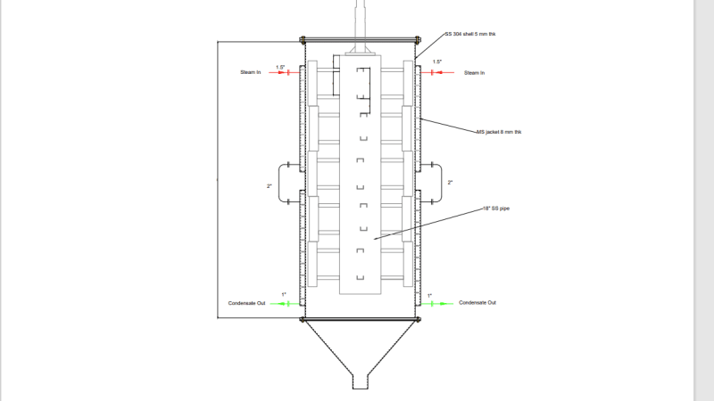
We have a jacket heated agitated thin film dryer in our plant . 6 months ago it bulged on the inside. We fabricated a new vessel and after running for 6 months, it again got damaged by bulging on the inside on 6 locations like a flower. What might be the reason for this? This vessel is empty on the inside with blades scraping the inside of the shell and outside it is jacketed and heated by 2 bar steam through spiral baffles. Please tell me your thoughts about possible reasons behind this? Is the thickness sufficient. Please tell me how to calculate the thickness for external pressure. I got stuck on the unsupported length since it is stiffened by spiral baffles.
 
Replies continue below

Recommended for you

Basic data is SS 304 5mm thick shell, #I thought we had dimensions but it doesn't look like it at present only this. Picture makes it look like 600 to 800mm diam

Screenshot__21_xpabky.png


Remember - More details = better answers
Also: If you get a response it's polite to respond to it.
 
Kwisatz, I also have such baffle in a "double-pipe" jacketed loop reactor. Those little baffle is to divert the flow, and only with very light weld, shall not be considered in any strength analysis, not to think it will play major benefit to the shell. Engineering judgment is to ignore its effect. Don't complain it works well for 3 months and why failed. The reason is all hidden in the design. Have you owned a car ? When will the car start breaking down or parts failed ? Why manufacturer only gives you 3 years warranty ? Same thing to the equipment, robust design by adding more cost ? or a poor design without considering many factors beyond code ? You have a dynamic vessel, not a "static" vessel that Div 1 code focus on. The agitator causing the problem that is beyond the code.
If I design it, here is what I will do:
1. The overall length from top flange to bottom flange is the overall length "L" per Div. 1 code for external pressure.
2. Use the difference of (steam inlet design pressure- minimum internal operating pressure) as the external design pressure to calculated he shell thickness per code. I try to maximize the difference. But you can use maximum steam operating pressure.
3. Condensation case: internal design pressure increased by 1 bar.
4. To account for unknown dynamic impact from agitator, I will increase shell thickness by 20-50% for more rigidity, due to soft SS. I will say at least use 1/2" thick, my gut feeling.
5. If you own a car and have done tire rotation and balance, that is another key issue why the equipment can fail: out of balance of the agitator blades that scraping around the shell. If low speed, may no be an issue. Our agitator used in vessel is well balanced by supplier who specializes in it. So how was the agitator made ? any balance done in design speed to avoid vibration ?
6. What kind of top flange ? Is it rigid enough such that when agitator rotates, it will not deform the flange or make the shell move like a wave or S shape ? That means, the flange and shell must be an integral rigid body.

Too many design issues just for two things "rigidity and common sense" which are BEYOND CODE.
Cost is another concern that you have to balance with reliability, such like car. Now you have 3 months warranty, to make it thicker and rigid will get you more. Dynamic is hard to predict.
Enough for this, GL.


LittleInch, Shell dimensions are 1200 mm ID x 3000 mm Height x 5 mm thick SS 304 material with circumferential weld at middle. Top jacket height is 1180 mm, bottom jacket height is 1280 mm. Jacket is 8 mm thick MS plate. Top jacket starts at 260 mm from top. Length between two jackets is 200 mm. Jacket ID is 1320 mm. Spiral baffles are 8 mm thick 40 mm wide stitch welded MS strips of pitch 120 mm. Steam pressure inside the jacket is 2-3 bar max. I don't think internal pressure in shell could go to complete vaccume since at bottom there is a 6" opening for salt to fall.
 
Update on my problem.
We did a little investigation and found out that a maintenance activity was done on the steam PRS at the same time as the vessel got damaged. Fitter wouldn't admit it, but he might've opened the bypass valve while working on the PRV and pressure might've gone up. Thanks for all ur inputs guys.
 
One of those situations where a manual bypass around a control valve didn't work??

I remove them wherever possible.

Remember - More details = better answers
Also: If you get a response it's polite to respond to it.
 
I don't think that's the only problem.
You obviously have difficulty expressing this through a drawing, so you cannot see the situation for a correct analysis.
Your information is confusing. First you said 2 bar pressure, then 3 bar.
What is MS?

Regards
 
MS = mild steel in this context.

But 1.2m diam at only 5mm thick is pretty thin for what could easily be 2.5 to 3 bar DP.

That's a D/t of 240.

stitch welded strips offer very little reinforcement so forget about them.

Remember - More details = better answers
Also: If you get a response it's polite to respond to it.
 
going through all the posts, I don't think the vessel was properly designed for 2-3 bar external load. This coupled with the gravity load plus some extra external pressure load due to condensate head may have caused the bucking of the bottom part of the vessel.
It's logical to think why the buckling is towards the inside of the vessel, not outside. I would have guessed that the buckling could also have been outward as the condensate would pull some vacuum when the jacket operation is stopped.
Another thought that comes to my mind is that it will take an appreciable jacket force to detach the welded baffle plates from the vessel wall. Is there, any instance that the MP steam PRV saw some excursion? I have assumed MP steam as your working jacket pressure is 3-4 bar.

GDD
Canada
 
Guys, I've attached the drawing file for the vessel, we dismantled the shell and found that the top side shell also got bulged inward but not more than the bottom one. PRS is set for 2.5 bar. You're saying it's too thin, but the old one worked for almost 7 years and the new one lasted for 6 months.
 
 https://files.engineering.com/getfile.aspx?folder=7a2c2b26-f53b-4067-9b0c-e0bee61d2153&file=ATFD_MEE-1.dwg
Do you have records of the internal and jacket pressures?
The old one may have survived because you never went to the pressure limits.
If any plumbing or controls were altered when the new one was installed, then you may have changed conditions enough to do this.

= = = = = = = = = = = = = = = = = = = =
P.E. Metallurgy, consulting work welcomed
 
Op,
Find out if the vessel was designed for both internal and external loads. What's the construction Code?

GDD
Canada
 
Edstainless, i already mentioned that a maintenance activity was done on the PRV while this machine was running. The PRS is in another plant, from there they have this one line that goes to this vessel in different plant. We're thinking the maintenance person might've opened the bypass for more than 2.5 bar while working on the said PRV.
 
GD2, This new vessel is just a replicate of the old vessel, nothing's changed, contractor made this vessel same as the previous one. Also I don't have any data for the old vessel.
 
So basically there was no design work?

Just "can we have another one please",,,

I think I can see the flaw here.

Maybe do some design to establish an acceptable factor of safety and then fit a pressure relief valve to the steam jacket?

Remember - More details = better answers
Also: If you get a response it's polite to respond to it.
 
LiitleInch,
Same contractor was involved in the fabrication of the original vessel. Old vessel was designed by a design firm with whom we doesn't have any contact with now. Contractor only has that drawing available. Also what's the problem in replicating the old design if everything else remains the same?
 
The problem is that you, as the operator, seemingly have no idea what the design pressure is for the steam jacket, what the vessel design code was or what the FoS is for the vessel to prevent collapse. Also not sure how you have a steam system entering a jacket with seemingly no pressure relief on it. You are probably correct that the technician did some sort of bodge to keep production going whilst he did something to the main pressure valve and over pressurised the jacket, but now won't admit it once the tank went bang.

So maybe the original design was for a lower steam pressure? How do you know if you have no contact with the designer?

You've had a vessel collapse which is potentially very serious. the jacket could equally well have failed and injured someone or done more damage, so you really need to see how and why this happened to prevent it happening again.

Virtually everyone here is telling you your vessel imploded due to excessive differential pressure greater than the design case, but now it seems you don't actually know what the design case was.

Also re-reading your OP it says your first vessel failed 6 months ago (after a few yeas of operation) and then you built an identical one and it failed also after 6 months. Does something not strike you as a bit odd there?


Remember - More details = better answers
Also: If you get a response it's polite to respond to it.
 
Where is the nameplate?
Without documentation, this pressure vessel is considered scrap metal. Therefore, it could never be put into service.
Try to contact a lawyer.

Regards
 
Is it a PV though? Its a steam jacketed tank which looks like its atmospheric pressure.

It might not classify under size?

I don't know how a steam jacket is thought of whether its a vessel or not?

Remember - More details = better answers
Also: If you get a response it's polite to respond to it.
 
Back
Top