Eng-Tips is the largest engineering community on the Internet

Intelligent Work Forums for Engineering Professionals

Jacking up a tank 2

Status
Not open for further replies.

Docbar99

Specifier/Regulator
Jan 15, 2021
13
0
0
US
I am looking to jack up a process vessel / tank / silo on load cells. The purpose to move the tanl just a few milimeters to help verify the accuracy of the load cells. I am in the process weighing vessel industry and know nothing about hydraulics.

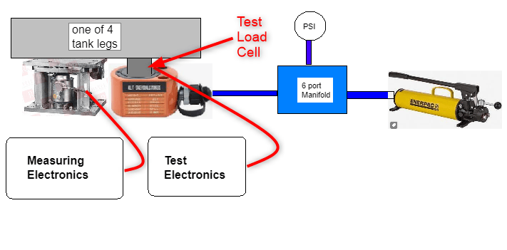
Whay I hope to do is to have a manual pump connected to a 6 port manifold with one hose connected to the pump, one hose connected to a pressure gage and 4 hoses connected to the jacks at each of the 4 lifting points. Between the jack and the load will be the a load cell that is part of the measurement system electronics.

The process would be to start with a fully loaded tank. Excersise the hand pump until contact is made and registered on the measuruing system electronics. Repeat for all 4 measurement points. Zero the system under test readout, zero the verification electronicc. Increase the hydraulic pressure in small increments and verify that the unit unde test matches the readings of the verification electronics. The test electronics indincation will increase and the system under test will decrease. If not introduce a calibration factor and repeat the test.

My questions are about equipment selection for the hydraulic components. My goal is to have four 20 ton low profile jacks.
This would give me 80 ton lift capability * 0.8 for a safe lift capacity of 64 tons.

1- For a slow manual process like this with a very low duty cycle, (maybe used a few times a year) what is the most important features or specifications are most important when selecting the jacks?

2- How to select the correct hoses / fittings?

3- any general suggestions / precautions.

I see 20 ton jacks for 500 dollars and cheaper ones for 100 dollars on Amazon, what is the difference between these ?
Hydralic_concept_ktm0cv.png
 
Replies continue below

Recommended for you


Your system will leak oil. All systems leak to some level. Depending on the pressure you have in your system, the leakage rate will lead to frequent cycling of the pump.

Your jack selection criteria is the pressure requirement and more importantly, the displacement of the pump. It's likely that your 4 jacks will have different leakage rates and they will probably have different levels of static friction.

All of this means that one fraction of a stroke of the pump or maybe one full cycle of the pump will cause each jack to move different amounts.


The hoses will be small and the pressure rating will depend on the levels of pressure you need in your system.

have you calculated the pressure required to generate 20T?


Depending on the loading of the jacks and the stiffness within each one, you will most likely find that depressing the level on the pump will result in one jack moving, while the other three stay still.

Also, as stated above, there will be leakage and that means your static pressure will decay or the jacks will retract a little if the pressure is constant.

I expect that you will have to operate the pump a few times per day. The frequency of operation depends on the leakage rate, which is a function of the pressure in the system. Also, what level of accuracy are you hoping for? If you expect a few mm of the displacement, your tank will need to be very stiff to reduce the strain. Otherwise you will just see one jack moving and nothing else.


@FluidPowerUser- Thanks for the fast response to my question. Let me explain a little more and please forgive my lack of basic hydraulics knowledge.

1- A more detailed explanation of the process- I forgot to mention that I was planning to add a needle valve on each manifold. I would start the process by opening one valve and pumping until I make contact with the load by observing a change in the displayed weight in the verification electronics. I then would shut the valve and repeat for each of the 4 points. At that point the I would be ready to start the test.

2- Next I would zero both displays.

3- Open all the needle valves an start pumping while observing the verification electronics until the target weight reading is achieved. I realize that lift may not be uniform on all 4 points, but this does not really matter as the 4 load cells are wired in parallel so that the voltage output is is the average of all 4 load cells. The job of the electronics is to display the average weight. Even if the hydraulic lift is unequal it will still apply a known pressure to the system under test.

4- The reason for using this approach is because some customers have huge tanks with no place to mount test weights which is the traditional way to test / calibrate a weighing system.

5- The test should take less than am hour to complete and then may not be used again for weeks or months. That's why I am not sure if I need to invest in the most expensive equipment.

6- About the PSI- I see that the jacks have a ton rating, but I am not sure exactly how to match a hand pump to the total lifting capacity that I need to lift. My first thought was that if you keep pumping
you will eventually get to the PSI needed to get to 80% of the jack rating.

7- Do you think that exercising one jack at a time would be better, I will take your advise on that.

8- Another question I had was if you think a longer stroke in the jack would produce a finer adjustment than a shorter stroke? The idea to make the system more universal was to use a low profile jack and if
and use some steel discs to make up for the height if necessary.


Let's go back to the basics of what you are trying to achieve here.

It sounds like you want to measure the mass of the tank - Correct?

What mass are you expecting? Mass x Gravity will tell you the force you will have. When you know the force, you can divide that by four and that will tell you what force each jack needs to develop.

The force divided by the area of the jack cylinder will tell you the pressure your pump needs to develop.

The pump uses a differential area piston and leverage to allow an average mass person to be able to operate the pump. For example, 32kg or 70 pounds applied to the handle will get you 700 BAR pressure or 10,150 PSI. How much do you need? To change the displacement, they offer bigger diameter pistons rather than longer stroke as you don't want to go above 45 degree stroke angle as the resolve forces increase and you'd need a gorilla to operate the pump.

If your plan is to build the pressure on each leg and then lock the pressure in with a needle valve, then you are on the right track, but you will still see pressure decay because there will always be some leakage over the needle valve and across the seals in the jack. It won't be a problem if the load on the jacks is short term. I am just saying that there will be some leakage over time, so don't expect the static pressure to stay the same or for the jack to hold position forever.

What does the tank sit on when you are not calibrating the electronics?
 
@FluidPowerUser- First I really appreciate the time & effort you have already given to me. I hope my lack of knowledge is not too frustrating for you.

Yes- I am trying to measure the mass of the vessel, but more importantly the weight of the material inside or the vessel. The weight indicator as part of the initial calibration process measures the empty weight of the tank before any fluids ate put into the tank. The normal process is to place a known amount of mass on the scale and tell the electronics how much weight you placed on. The scale then calculates a scale factor in for instance (mv/kg) and then uses that to indicate the weight value after subtracting the empty tank weight. Since large tanks may need tons of weight that is not safe / practical we simply use load cells that have a known mv/kg rating and that gets us pretty close in most cases. But if there are improperly designed systems with too much deflection in the support beams or rigid pipe connections the theoretical mv/kg calculations will not be accurate. What I am proposing is a alternate way to apply force to the same load cells using the jack to apply the force to both the system under test load cells and the test load cells. The test load cells are in a perfect position to give accurate results as there is no system errors. The test load cells will give an accurate reading in the positive direction. The unit under test will start with as close to full as possible. As we jack it up, the weight will decrease and if perfect it will match the test load cells, but opposite. If not perfect, a new scale factor is calculated.

If the jack were to deliver a lower pressure that expected, more pumping would be required until the setpoint is reached. (of course safe limit * 0.8 or less)

The actual setpoint will vary depending on the customer's tank. I was thinking that with four 20 ton jacks I could go to a maximum of 64 tons. Most often the tanks have less than 50% of that capacity.

OK to see if I understood what you said- I will make an example- The tank empty weight + contents = 25 tons = 245000N or 24983.05 kg/force. (25,000 / 4 = 6.25 kg/jack)

Pump example- [TECNICAL PARAMETER]--- Oil capacity: 400cc | High pressure output: 600kg/cm2 | Length: 13.4”/340mm | Weight: 7.7lbs/3.5kg | Oil pipe coupling with: ZG3/8 thread | Hose : 31”/0.8m

So in the manual pump data- 600kg/cm2 ( also says 400 cc which I would assume to be the area inside the cylinder) I believe Force = Pressure x Area, but we don't know the area. For Area- Area =π × r2,
but we don't the radius.

I found online r = square root of (Volume / 3.14 x h)
r= square root of (400 / 3.14 x 34 cm)
r= square root of (400/106.76)
r= square root of 3.746
r= 1.936

Then area= 3.14 x radius
area= 3.14 x (1.936 cm)2
area= 3.14 x 3.748 cm2
area= 11.77 cm2

Converting 600 kg/cm2 to Pascals = 5.88399e+007

Back to Force = Pressure x Area = (5.88399e+007 x 11.77) = 692,545,623 N)

Convert to kgf = 6,745,528.29 kgf.

THIS SEEMS WAY OFF- not sure where I went wrong.

You asked what does the tank normally sit on- It sits on what we call the "Mounting Kit" which houses the load cells. There are usually 3 or 4 of these in a system.

 
 https://files.engineering.com/getfile.aspx?folder=65081ecf-0f6d-435b-9f79-e3ab666f324d&file=jacking_system.png
I am happy to help. It's not a problem.


This isn't quite right and may be where you are going wrong on your calculations.

Tank + content is the total mass. Force is mass x acceleration. Force is Newtons, Mass is Kg, Acceleration is gravity

You have 25x10[sup]3[/sup]kg x 9.81 = 245.25x10[sup]3[/sup]N or 245.25kN

245x10[sup]3[/sup]/4 = 61.3125x10[sup]3[/sup]N on each jack


400cc is the volume of the tank

600kg/cm[sup]2[/sup] = 588.4 BAR or 5.88x10[sup]7[/sup]Pascals as you have calculated.

You know that Force = Pressure x Area

The required Force is 245.25x10[sup]3[/sup]N

The max pressure is 588.4x10[sup]7[/sup] Pascal (1 Pascal is 1 Newton/m[sup]2[/sup])

Area = Force / Pressure

Area = 245.25x10[sup]3[/sup]/588.4x10[sup]7[/sup]

To achieve your required force at the jack the head area has to be 4.1638x10[sup]-3[/sup]m[sup]2[/sup]

The diameter of the jack would be 72.8mm - That number aligns with jack cylinders that are available with this sort of force and pressure.

Bearing in mind though, that is just one jack. It demonstrates the power to weight ratio of hydraulic actuators. You will have 4 jacks, so the pressure in each jack will be 25% of the total max pressure - 5.88x10[sup]7[/sup] / 4 = 1.47x10[sup]7[/sup]Pascals or 147 BAR or 2131.5 PSI.

To answer your earlier question about the difference between expansive jacks and cheap jacks, it's about the number of times you can use them before the seals split or connections start to leak. Materials that can withstand high numbers of cycles between 0 - 700 BAR are expensive. Hose material, seals, threads, couplings...they are fail early if they are made of low cost materials.
 
@FluidPowerUser- Thanks for your continuing support.
I will try to work through these problems myself so that it sinks in better.
 
I did not see it mentioned, but hydraulic jacks in parallel will not move in unison unless the flow to each jack is controlled to be the same. Each jack needs its own pump or valve. Without this, one jack will break its static friction and extend all the way before the next jack starts to move. The rigidity of the tank may mitigate some of this but the tank will not stay level as it rises and the balance will change, making the problem worse.
 
@Compositepro- Thanks for your feedback. FluidPowerUser did warn me about that. What I am pprepared to do in order to minimize that effect is to have a needle valve on each line and move them one at a time. Also- the load cells are wired in parallel, so if one load cell gets more force than one of the others the measurement electronics will take an average of the four load cells before posting the weight reading.

Do you think it may work if we do one at a time?
 
@FluidPowerUser-

I worked through the problem and was off your numbers in two places- not sure what I did wrong.
Sample Problem:
The tank empty weight + contents = 25 tons = 245000N or 24983.05 kg/force.
F= MA
F = 25 t = 25,000 kg x 9.81 =245,250 =2405kN

2405kN / 4 = 626kN on each jack
------------------------------------------------------
400 cc is the volume in the cylinder.
The output of the pump is 600 kg/cm (squared)
MAX Pressure = 600kg/cm( SQ) = 588.4 BAR or 5.88x10 E7 Pascal’s
Force = Pressure x Area
Force = 5.88x10 E7 x Area. But first find Area.
Area = Force / Pressure

Area = 245.25x 10E3 / 588.4x10 E7
Area = 4.1638x10 E-3 m (sq) ( I got 0.000041681 = 4.168E-5 )
Find the diameter of the jack.
d= 2 * SQRT(A/3.14)
d= 2 * SQRT( 0.000041681 m / 3.14) = 0.00728 m = 7.286 mm (should be 72.8 mm)

If you don’t mind, can you show me where I made the error?
Question- why did we need to get the diameter of the jack?

I appreciate your advice about using cheap components.
I am considering Enerpac parts, they are expensive, but seem to be a decent company with allot of resources online.
I was considering this pump.
 
Hello...

You have a scaling error.

Force is 245,250N and that is 245.25KN. You have used 2405KN, almost factor of 10 out.

You corrected it further down in equation for the area, but you also moved the decimal point for the pressure, but then you also corrected that.

Your last equation has the decimal point in the wrong place for the area too. 4.1638x10[sup]-3[/sup] is 0.0041638, you have it as 0.000041681?

I use PIxD[sup]2[/sup]/4 for area and resolving that for D, the diameter. It's the SQRT(4xA/PI)and I get 0.0728m, which is 72.8mm.

Using your equation that is PIxr[sup]2[/sup] resolved for the diameter, you get 2xSQRT(0.0041683/PI()), which also comes out as 72.8mm. It looks like it's the error in the area value that is throwing your diameter value out.

Checking the diameter of the jack is really a sanity check to see if it lines up with the jacks available. The good news is that jacks with a comparable diameter are available and they have same lift force if you apply the same pressure, so it all lines up.

Enerpac is good stuff, but as you see, very expensive.
 
@FluidPowerUser- Thanks again for your awesome & prompt support. If you know of another brand besides Enerpac that you would recommend that will be reliable at a better price, let me know.
 
Status
Not open for further replies.
Back
Top