Continue to Site

Eng-Tips is the largest engineering community on the Internet

Intelligent Work Forums for Engineering Professionals

  • Congratulations cowski on being selected by the Eng-Tips community for having the most helpful posts in the forums last week. Way to Go!

Jamb Screw Design—Shear‑Only or Prying‑Tension?

jsu0512

Structural
Aug 1, 2017
32
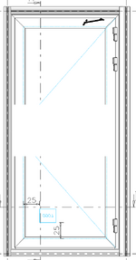
I'm reviewing the screw that anchor the aluminum jamb of a swing door to the supporting structure and i'd like your opinon on the screw design.

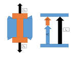
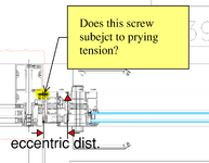
My engineering colleague believes that the screws that anchor the door's jamb to the substrate should be designed for prying-tension load due to the twisting along the jamb created by load eccentricity between the glazing gasket (where the glass bears) and the mullion-to-substrate interface. And that approach would lead to very tight screw spacing...

My view is that the door's jamb wouldn't twist like he believe because door jamb is tied to header / sill frame rotational restraint that jamb can't rotate; the jamb, header and sill frame would work together as one stiff rigid portal frame. With that twisting locked up, the perimeter screws would carry shear load only. I'm attempting to demonstrate this to him by (1) showing that the head/sill to jamb screw connection provide adequate rotational restraint relative to the twisting moment and (2) verifying that the jamb's torsional strength greater than the calculated twisting moment demand.

Does treating the door portal frame as rigid and therefore designing the perimeter screw for shear load alone seems reasonable to you, or should i account for prying tension load as my colleague suggest?
1744518639043.png
1744518674750.png
 
Replies continue below

Recommended for you

Like many glazing systems details I have worked with in the past, I don't believe the correct answer is clear. But personally, if it a door for people, at a height of 80" or more, I would be skeptical of the ability of the thermally broken frame and connection to the top and bottom components to be stiff enough in torsion to transfer these loads.

Any chance there will be / was a performance mock-up?

It appears that the negative and positive wind load conditions will be be resisted by different structural mechanisms, so if you haven't considered this already, it might be worth looking into (potentially with a group of screws near the door catch to resist the presumably higher negative wind load reactions, and potentially larger spacing along the full lengths for the positive wind load case).

Assuming that the pullout of this screws from the mullion is the controlling factor, another potential option might be either thickening the side wall if possible, or adding a plate / channel to beef up the pullout capacity.
 
I appreciate your feedback. I was actually trying to approach this from a fundamental engineering perspective. Let’s say we’re dealing with a non-thermally broken extruded aluminum frame — in that case, would my assumption be valid that the screw connections would primarily experience shear only, as long as the top and bottom of the vertical frame are torsionally restrained and the frame itself has sufficient torsional rigidity?

If, however, the torsional strength of the frame is not adequate, would the screws then start to experience prying tension? My thinking is that before any prying action occurs, the screws would first be subjected to shear forces caused by the twisting moment — especially since the screws are connecting two frames along their length, and one frame is undergoing torsion.

Does that make sense? I’d appreciate your thoughts.
 
Theoretically, in my mind, the torsional stresses (and resulting rotations) will likely develop additional tension in the fasteners incrementally, and not just if/when the torsional strength is reached.

In reality, it's less clear what will happen. I would think that the "strong axis" stiffness of both the stationary jamb framing and the door framing, the spacing, location and stiffness of the screws (cantilevered out of the relatively thin aluminum frame) could all impact how this would actually behave. For example, if you just had two strong screw connections at very top and bottom, I would think the reduced twist at the frame at the anchorage locations should develop less tension due to eccentricity, when compared to a theoretical condition with screws at 8"o.c.
 
first let me state , this not my specialty.
but I been researching bolted and screw
preload requirements., the stiffness of the bolted or screw assembly.
the preload on the clamped members
will (and forgive if I don't state ot it exactly correctly ) the members maintain most of
the load. if the screw has the correct friction
on flank of the thread and the correct washer or head washer. it will apply the correct preload. the preload and torque required will be based on that exact geometry.
the clamped members will maintain the the shear load. there will only be torsional moment if the screws loose preload.
or the member are stiff enough.
Yield Strength.
please as I said I am a novice in this aspect
and please critique carefully.
 
AI Overview
1744653110803.png
1744653110953.png
+4

Bolts, Preload Explained | by Andy | Medium

To calculate the preload on a screw, you typically multiply the required stress (often a percentage of the screw's yield strength) by the screw's cross-sectional area. Preload is the tension created in the screw when tightened, which then creates a compressive force on the connected parts.

Here's a more detailed breakdown:


1. Determine the Required Stress:
  • Yield Strength:
    Find the yield strength of the screw material (usually in psi or MPa). This is the stress level where the screw will start to deform permanently.

  • Percentage of Yield Strength:
    A common approach is to use a percentage of the yield strength for the required stress, typically 75% to 80% of the yield strength.

  • Calculation:
    Multiply the yield strength by the chosen percentage to get the required stress.

2. Calculate the Cross-Sectional Area:
  • Formula:
    The cross-sectional area (A) of a screw is calculated as A = πr², where r is the radius of the screw.
  • Diameter:
    Since you typically have the screw diameter (d), use the formula A = π(d/2)² = πd²/4.

3. Calculate the Preload:
  • Formula:
    Preload (P) is calculated by multiplying the required stress (σ) by the cross-sectional area (A): P = σ x A.
  • Units:
    Ensure your stress units (psi or MPa) are consistent with your area units (in² or m²) to get preload in the desired units (e.g., lbs or Newtons).

Example:
Let's say you have a 1" diameter, Grade 8 screw. Its yield strength is 130 kpsi (130,000 psi).

  1. Required Stress: 0.75 * 130,000 psi = 97,500 psi.
  2. Cross-Sectional Area: A = π(1 in)² / 4 ≈ 0.785 in².
  3. Preload: 97,500 psi * 0.785 in² ≈ 76,500 lbs.

Important Considerations:
  • Nut Factor (K):
    When relating preload to torque, a nut factor (K) is often used. K is a coefficient that accounts for friction in the threads and other factors, according to Ansys Innovation Space. Torque (T) is calculated as T = K * D * P, where D is the screw's nominal diameter, and P is the preload.

  • Preload vs. Clamp Force:
    Preload is the force applied to the screw, while clamp force is the force exerted on the parts being joined. External loads can affect clamp force, potentially reducing it to zero in some cases, says Machine Design.

  • Measurement:
    While calculation provides an estimate, measuring preload using strain gauges or other methods is often necessary for critical applications, according to lycos.com.
 

Part and Inventory Search

Sponsor