Continue to Site

Eng-Tips is the largest engineering community on the Internet

Intelligent Work Forums for Engineering Professionals

  • Congratulations waross on being selected by the Eng-Tips community for having the most helpful posts in the forums last week. Way to Go!

joints in seawalls 1

Status
Not open for further replies.

mid-tn-mustang

Structural
Jul 17, 2017
2
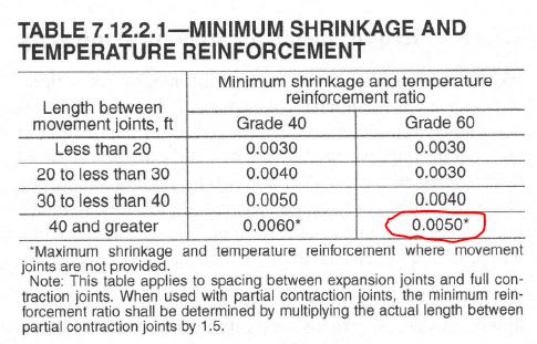
Hi i noticed a thread from a long while ago that several indicated that as long as the seawall had greater than 0.5% horizontal reinforcing that control joints were not required. Can anyone advise me on where that comes from in the ACI. I am working on a seawall project and would to obviously eliminate as many joint as possible. thanks
 
Replies continue below

Recommended for you

I do not remember this thread that you mentioned. Perhaps if you linked to it then we could all reference it. I am not aware of any code requirement for this purported 0.5% horizontal reinforcing.... but the theory is that enough horizontal reinforcing will keep any cracks tight so that they are not apparent. I'm not a big fan of this brute force approach to designing a seawall.

I have designed many seawalls (several different types) and I always put control joints in them. Are you worried about corrosion at the joint locations? That's easy. Stop all your horizontal reinforcing 3" short of the joint and dowel across @12" o.c. vert. with smooth GFRP bars that are 2'-0" long. I either use 1", 1-1/4", or 1-1/2" dia. GFRP depending on whether or not this seawall is located adjacent to a roadway as well. You don't need to worry about corrosion at the joint because your dowel is corrosion proof. There are several other things you should keep in mind such as increased clear covers elsewhere and really good specified marine concrete.
 
I think I know where that comes from....

ACI 350 has recommendations for control joint spacing, and a .005 is required when no joints are provided.

Capture_dzkqbz.jpg
 
thanks i like that idea with the gfrp and holding the seel back. Yes corrosion is a concern. How have you done an expansion type joint that will minimize corrosion as well provide for adequate water tightness and minimize the sands/ fines in the back fill from coming through
 
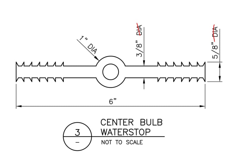
PVC ribbed waterstops
 
I wonder if you could use FRP plates in one of the plate dowel systems. They go up to 3/4" thick plates.

Capture_xmksdr.jpg
 
cvg beat me to it. PVC ribbed waterstops with center bulb. Based on your anticipated expansion, size your joint filler appropriately within the joint.

Some people prefer to form a keyway with PVC waterstop at the expansion joint details but I am preferential to the smooth GFRP dowels. The only two things you need to ensure is that the location of the PVC waterstop and GFRP dowels don't conflict and that your dowels are installed orthogonal to the joint. I like to add some vertical GFRP runner bars each side of the dowel and each side of the joint to try and keep that dowel bar stationary during concrete pour.
 
strctpono - do you have a preference for waterstop length? is 6 inch adequate or do you recommend 9 inch? i have heard that the longer is easier for contractors to position correctly, but not sure I buy that.

waterstop_bnw6jc.jpg
 
You mentioned control joints. I don't think engineers use the terms control joint and contraction joint consistently. You need to define how much reinforcing is crossing the joint (if any), and what type of surface profile the joint has (if any). If there is a groove, then do you use poly sealant? Another maintenance item.
Center bulb WS is usually used at expansion joints, not control joints. Even with the best intentions PVC waterstops can fold over; only use 9" PVC WS at expansion joints. Better to use 6". At construction joints, of course no center bulb is used.
For walls 150 ft or less, I use 0.6% horiz steel and no control joints. Only construction joints and expansion joints. Of course, decent and qualified engineers do indeed use control joints (and USACE seems to approve of it). Control joints in water-retaining structures and sea walls is up for debate.
Most wall placements are 50ft long or less to minimize early shrinkage; a construction joint (full reinforcing continuous thru, monolithic behavior) is at most joints, then expansion joints at 150 ft.



Excellent point ATSE. I complain about this regularly when I review drawings.
 
Can you two elaborate on your definitions of control and contraction joints? For instance, I consider a 'control joint' to be a joint to control where cracking will occur. I consider 'contraction joints' to be 'expansion/contraction joints' and detail them such that the wall can expand and contract with temperature and maintain out of plane integrity. Curious to see if my definitions match yours.
 
pham,

To me

control joint or dummy joint - a formed or saw cut recess in the concrete, where we hope it will crack - dik had a good picture recently - all reinforcing steel goes through the joint.

construction joint - interruption in a concrete placement; no formed or saw cut recess; all reinforcing steel goes through the joint.

contraction joint - "sort of an expansion joint". Perhaps, we should bring back "shrinkage joint". Two concrete placements that butt up against each other. The reinforcing steel doesn't go through the joint. We typically put these in retaining walls and abutments every 30'.

expansion joint - a formed joint with a key and compressible filler material. The reinforcing steel doesn't go through the joint. We typically put these in retaining walls and abutments every 30'.

Most of my work is with public agencies. Some define the terms in their standards; some don't. What irks me is when people call out something but don't explain it. Reminds me of something I learned many, many years ago in a construction progress meeting. The contractor's super was arguing with the owners rep and he said: "I just want three things from you: 1) what do you want me to build? 2) how do I get paid for it? & 3) Please don't ask me to read your mind." That' stuck with me, particularly #3.

 
bridgebuster said:
control joint or dummy joint - a formed or saw cut recess in the concrete, where we hope it will crack - dik had a good picture recently - all reinforcing steel goes through the joint.

If you are putting control joints into a reinforced slab it is unlikely to crack at the control joints. The reinforcing provides far too much restraint especially at corners. If you must mix reinforcing with a control jointed slab (ideally not and you simply account for map cracking by limiting widths via increased RFT ratio or just don't use reinforcing), then you should do something more to weaken the joint such as cutting every other bar.

CWB (W47.1) Div 1 Fabricator
Temporary Works Design
 
bridgebuster - thanks. Sounds like my definitions match yours pretty closely. I'm curious, though - your expansion joint and contraction joints are identical in all but the key. 1) how do you control out of plane differential movement/load transfer? 2) If you provide both at 30', are they offset 15' from one another?

Enable - I agree. I usually detail a cut bar/wire at crack control joints if I have reinforcing.

For what it's worth - I don't do a ton of concrete. Mostly slabs on grade or slabs in form deck. The occasional short retaining wall, but most folks around here prefer masonry for that. All of my seawalls/bulkheads have steel sheet piles for large projects or timber for smaller jobs. A couple composite sheets - those are pretty terrible.
 
phamENG - a blunder on my part, I forget to state that we place a shear key in the contraction joint. Per the DOT specs, same thing goes for construction joints.

Enable - we don't put control joints in bridge decks; just the paraapets.
 
hmm, in my mind concrete control joint and contraction joint are synonyms. I do not use the term contraction joint at all and I feel control joint is used more often nowadays. But I think they are in practice the same thing.
 
I suppose my defintion is slightly different. For me, control joints are contraction joints and the term is used interchangeably.

cvg, I also follow similar guidelines as ATSE. 9" waterstop with ribs and centerbulb for expansion joints and 6" waterstop with only ribs at control/contraction joints.

bridgebuster said:
we don't put control joints in bridge decks; just the parapets.

We call those deflection joints.
 

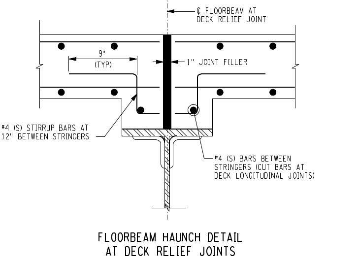
STrctPono - what do you mean by deflection joint? A few years back, I did a deck replacement on a mile long viaduct with crazy framing. One section had floorbeams with "deck relief joints". We mimicked what was done 80 years ago.


drj_o0jecr.png
 
I was referring to your comment on joint in railings/parapets on bridges. We call those deflection joints. They contain a gap. No joint filler. Chamfered edges. No dowels or keyway.

Interesting detail on the deck joints. I've never seen that.
 
See attached USBR tech memo re: concrete joints. CGSL-8530-2016-13
One valuable thing they did was compare joint vernacular across the different organizations (USBR, ACI, PCA, ...).
This thread won't clear up the industry slop regarding terms.
Make sure your drawings are crisp and clear regarding reinforcing continuity (0%, 50%, 100%) across each joint type.
 
Status
Not open for further replies.

Part and Inventory Search

Sponsor