Continue to Site

Eng-Tips is the largest engineering community on the Internet

Intelligent Work Forums for Engineering Professionals

  • Congratulations KootK on being selected by the Eng-Tips community for having the most helpful posts in the forums last week. Way to Go!

Ladder Framing for Roof Outriggers 5

reverbz

Structural
Aug 20, 2024
54
Hey Guys,

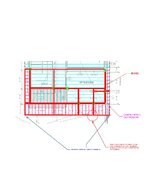
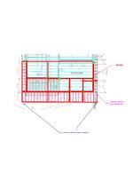
I'm trying to frame some outriggers in a wood residential building. See below for what I've initially drawn trying to use a ladder framing approach. the light blue are typ. TJI's. The red are beams and the green are where I can locate posts. There are openings below these beams so there's no wall or posts that can be added. I think the main issue I'm running into is framing the corners of the outriggers. I end up with 2 cantilevered beams and I'm trying to think how we can get around that. Do you guys think my drawing looks reasonable? Should I just have them do steel beams instead even though this is residential? Do you have any ideas on the corners?

Thank you!LADDER FRAMING.jpg
 
Replies continue below

Recommended for you

Similar to the framing on the left side. The corners are picked up by the cantilever beams on the sides.
 
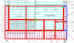
@dik @RontheRedneck the problem I'm seeing is that my beams are essentially cantilevers going to the corner on each side. I need them to be supported at 2 points. and as of now they're only supported at 1. I've attached another image where I've circled the area I'm wondering about. What does this connection look like so that the beam is supported at 2 points if it's wood?CONNECTION QUESTION.jpg
 
If this must be wood, you need more columns/supports. I understand the desire for minimizing them etc. But the final layout can't defy gravity. Work with your architect/desirgner and find somewhere to put a column near that inside (thick red line) corner and then cantilever some framing out to the corner.
 
Those side overhangs are what? a foot? Cantilever the rim members to pick up the corner. That's how these are typically framed, and they 'work'. Proving that reality isn't very hard, though to meet code some of the connections have to be beefed up a little.
 
@phamENG the problem is I'd need 2 support points for the rim beams. I don't see how I can do that unless there's a way to do a connection where I circled.
 
You have lots of supports at each of the overhangs from the rafters that are cantilevered along that wall. Obviously some of the values of these reaction vectors will be negative...

1731600581812.png
 
@phamENG If the rafters are supporting the rim beams they're just cantilevered though right? I'm not familiar with how to make that work with wood rafters
 
material doesn't matter (at least not until you start detail and selecting sizes). Cantilever your overhangs wherever you can. You'll have the primary framing direction - that's easy. extend the rafters out to form the overhang. in the other direction, come in whatever distance you need and turn framing toward that wall and cantilever those to form the overhang in that direction. Then use the rims in each direction to cantilever off of the overhangs and meet at the ends.

Now, if you don't have any walls below because windows go right up to the ceiling/soffit and they're trying to make a wood building look like a concrete building...tell them to add a column or let you design with steel and concrete.
 
dik - thanks, I could see it above. the problem is that there are really thick lines drawn all over the plan, so I don't know what's actually going on below.
 
@phamENG I think you got it which is that there are openings to the ceiling height under these red lines on the exterior walls. They're trying to say they don't want any other columns but it sounds like they are going to have to add one or we just use steel which seems better in this case. Just wanted to see if there was any way to make it work as is.
 
I'm with pham on this one, this appears to be a fairly simple and straight forward framing situation, with inverted hanger and/or 45degree struts at the corners carrying the load back to the walls. Difficulty for us is understanding your drawing, it's not clear enough what is bearing and where, with the heavy lineweights used.
 
@ChorasDen essentially, where you see red are beams. there is no wall/column space except where you see the Lime Green. My primary issue is I don't see how I can avoid having framing with 1 support only which doesn't work for wood in my experience.
 
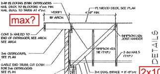
I feel like you're making this more complex than it needs be. Your drawing feels like a flat roof, but you get the idea, perhaps.


Outrigger detail.jpg
 
@lexpatrie The issue I'm running into there is the lack of space at the ceiling. I guess I could theoretically run them on top of the beams if I can get say 2x4's to work. Thanks for showing the detail it helps to visualize.
 
The only other way that I'm aware of, then, would be to do diagonal girders going out to the corners. The connections get a bit...iffy.
 
For your circled condition, we have seen this condition previously. Our solution was to provide a double angle connector at the end of the cantilever beam attached to the beam with through bolts. The "flange" legs of the angles would be flush to the inside face of the rim beam with a steel plate on the outside face of the rim beam, attached with through bolts from the flange legs to the outside plate. Granted, you Architect will probably have to get a little creative with the finishes...
 

Part and Inventory Search

Sponsor