Continue to Site

Eng-Tips is the largest engineering community on the Internet

Intelligent Work Forums for Engineering Professionals

  • Congratulations cowski on being selected by the Eng-Tips community for having the most helpful posts in the forums last week. Way to Go!

Lag Screw Withdrawal from Top of LVL

Status
Not open for further replies.

HDStructural

Structural
Apr 24, 2024
123
Hello,

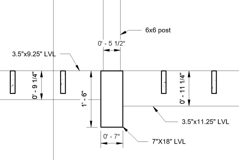
I am designing a garage with an LVL floor beam that supports a 6x6 post going up to the roof. Since it goes up to the roof, there is uplift on this post.

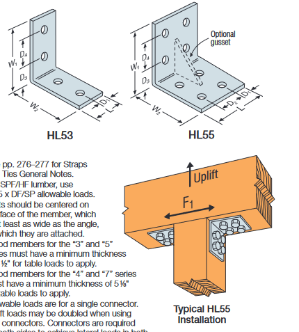
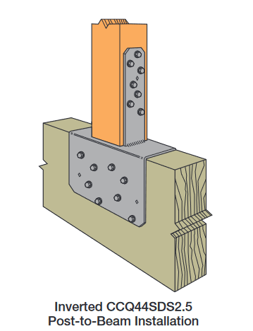
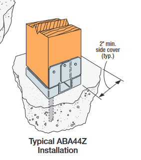
I am looking to anchor this post into the LVL with a concealed connection that won't stick out too much. I am planning to use Simpson Strong Tie's ABU type connection. I am aware this is typically used in concrete.

My question has to do with the design of the 1/2" anchor which would be a lag screw loaded in withdrawal from the top of the LVL. The withdrawal table for lag screws in NDS (Table 12.2A) notes that it is for withdrawal in the side of the member. This connection would be into the top of the member, which is similar to the end for an LVL. Would I just apply the end grain factor for lag screws in withdrawal (0.75) and call it a day?

I'd get my withdrawal values for g=0.50 which is the equivalent specific gravity for microlam LVL's.

Your thoughts are appreciated.

Screenshot_2024-06-17_150713_fvppi2.png
 
Replies continue below

Recommended for you

I would use a connection that puts the fasteners in shear, not in tension.
 
SWComposites, I agree with you, but am trying to determine if this is practical at the client's request.
 
Don't like this idea. An ABU/ABA isn't concealed on the post side so just use a regular post cap and flip it upside down.

Simpson makes a concealed connector I believe if you need it totally hidden. Or have them fabricate a custom connector with a knife plate in the beam. If it's going to be exposed you're probably better off just using one of the decorative Simpson brackets rather than trying to conceal it.
 
Seems like a bad idea. Look at a Simpson BC46
 
So the post sits on the LVL and you want to drill upwards through the LVL into the post?

Or you're drilling down into the LVL from above? Is that ABU even rated for an uplift load?

Either way the way LVL are made this is basically screwing into the edge of plywood. There are probably values for this situation, but a lag screw is larger diameter, lacks redundancy and is prone to separating the plies, particularly if the two required pre-drill diameters for the lag screw are not properly done.

On a related note, the LVL can't be pressure preservative treated, so a PSL which is wolmanized, or a preservative treated glulam/naturally decay resistant glulam may be a better idea, and then you are dealing with the corrosive/preservative versus the lag screw (or not).

I'd prefer a fastener(s) that goes into the face of the LVL/PSL beam. There are also probably dimensional mismatches to address between the post and the LVL/PSL width. What you are doing sounds a bit more like a column cap is intended to handle this (although it's upside down).
 
I have attached a snippet of a plan view and a section cut showing what is going on.

Screenshot_2024-06-18_084301_znjxf8.png


Screenshot_2024-06-18_084323_rgjupu.png


The post is a 6x6 and the LVL supporting it is 7" wide so they do not align perfectly. The net uplift on the post is around 1800#.

I also thought about using HL angles per below. This would have more redundancy as there are multiple lag screws that would be used, but another problem that I see is drilling 1/2" to 3/4" wide holes into the top of the LVL. That could take away more than 10% of the LVL's width which would push it to being overstressed.

Screenshot_2024-06-18_084403_mui0eq.png


The best option for simplicity is the CCQ connections but they are bulky and also complicate the LVL connections framing into the sides of the 7"x18" LVL. I think I will have to go with that though, unless the HL angles could be feasible somehow (which I don't think they are). I can figure out the side LVL connections with the CCQ in the way.
Screenshot_2024-06-18_084345_yaqy3g.png
 
Well, I did not realize you beam was 7" wide and you uplift was 1,800 lbs. My BC46 idea obvs. will not work then.
I can't think of an easy solution for you other than CCQ connector you show (assuming you can get the correct size).

"That could take away more than 10% of the LVL's width which would push it to being overstressed"

Wow, 99.9% of all LVL's I spec are deflection controlled. This must be a short span.
 
It is at around 92% stressed in bending and 94% for deflection, 24' span. So it is deflection controlled, just barely.
 
If you are worried about the adjacent connections use a smaller inverted post cap like XR said and then change the post to 5.25"x7" to match the width of the beam and use a couple of straps to resist the uplift. Much easier to put a hanger over a strap than a CCQ or bulkier column cap.
 
HDStructural said:
It is at around 92% stressed in bending and 94% for deflection, 24' span. So it is deflection controlled, just barely.

Looks like you are designing for L/240 TL deflection +/-. I usually don't go under L/480 so that is why mine are almost always deflection controlled.
 
jerseyshore, good thought. Thanks

XR250, is that a code requirement or more of a best practice? I accounted for long term deflections in my L/240 TL and there is no ceiling or anything underneath this LVL.
 
I feel like it is best practice as, in my experience, LVL's sag more than the calcs would indicate and it prevent call backs.
 
Weyerhaeuser Specifier's Guide TJ-9000 has guidance for spacing of nails installed into the narrow face of LVL's. Increased spacing is required to prevent splitting of the laminations. It does not mention screws or lags, and it does not mention direction of load.

The same document says not to install bolts or screws into the narrow face of LSL or PSL columns when installing post bases, caps, or holdowns that will be loaded in tension from uplift. I think we can deduce that splitting between laminations is a concern.

None of these is exactly the situation presented in your OP, but they should give you pause about installing into the narrow face of SCL beams.

Furthermore, I assume your 7x18 LVL is actually 4-1.75x18 LVL's? If so and if you are installing along the centerline of the top of the beam, then you would be installing the lag into the planar interface between two LVL's. I would not expect this to behave the same as a solid piece for holding a screw loaded in withdrawal.

All said, I would either contact the LVL manufacturer for guidance on installing lags loaded in withdrawal into the narrow face, or I would look for a way to install fasteners loaded in shear into the wide face.
 
If this is a residential garage...

Is it a floor? The issue I have with residential is it's not clear what the load case is, compared to the IBC. "structural member" in the IRC versus "construction" in the IBC. So triggering.

2021_IRC_Table_R301.7_Allowable_Deflection_of_structural_members_txkvdp.jpg
2021_IBC_Table_1604.3_Deflection_Limits_wxe9gs.jpg
 
Is this to be a finished space or an unfinished space (e.g. storage, workshop, etc.). If unfinished space I would definitely go with the CCQ. Personally, I wouldn't mind the appearance of it at all in an unfinished space. If it's to be finished, then simply cover the CCQ with trim, gyp board, etc.
 
I still think attaching fasteners to the top side of an LVL has grain/splitting issues. I don't have any solid documentation there's a reduced capacity or it's a no-no, but I think it's best to avoid it.
 
Simpson has done research and large diameter dowel fasteners perform poorly in the narrow face - much lower than expected. This is in the context of shear connections, but I think it follows that withdrawal capacities would be similarly impaired. You'll form a splitting force between plies as it pulls, which would neuter the capacity a bit.

 
Thank you all for your input. I will be going with a shear connection into the sides of the 4 ply LVL to get the uplift capacity.

For deflections, I assume the values listed in IRC are for live loads only, except for the masonry lintel. I see it isn't clearly called out though. The values listed in IRC match the values in IBC for L or Lr for the most part. My D and L deflection are each less than L/360 and TL is under L/240 with long term deflection considered. I think I am good to go.

Thanks all.
 
Remember that those are code minimums. In wood construction, they will almost always lead to problems. Footfall vibrations are a big issue with these 'soft' floors. There's a paper from Virginia Tech on the subject - I think they published as an article in fine home building. They go into a full vibration analysis of a wood floor. They also acknowledge that a level of analysis that high is beyond the budget of most design firms doing houses, and so they recommend designing to a live load deflection of L/480. Some will go a little further and use that for joists, but limit beams to L/600 for live load and L/480 for total load. This results in a stiff floor that is unlikely to make the plates rattle as you walk by the China cabinet.
 
Status
Not open for further replies.

Part and Inventory Search

Sponsor