Continue to Site

Eng-Tips is the largest engineering community on the Internet

Intelligent Work Forums for Engineering Professionals

  • Congratulations KootK on being selected by the Eng-Tips community for having the most helpful posts in the forums last week. Way to Go!

Large Deflections in Concrete Slab Without Cracking 6

Status
Not open for further replies.

Rdar43

Structural
Apr 25, 2022
19
I have an unusual issue on a project where there is a concrete slab that is deflecting 2.5" in the worst location only under construction loading. The two-way slab was designed using RAM concept and from the results, there should only be 0.6" of deflection occurring under construction. The area in question is a 33' span, the slab is 10" thick with an f'c of 5,000psi.

I've gone to the site and confirmed the deflections but strange part is there was no visible cracking on the top or bottom of the slab. The slab was poured all in 1 day and there were no visible construction joints in the slab either. I also noticed that there were larger than expected deflections throughout the slab, not just at the worst case condition. At 1st we thought that the contractor may have pulled the forms off to early as they pulled them 15 days and didn't reshore but the concrete break tests indicate roughly 4,000 psi at just 7 days (High-range ware reducers were used in the mix). It's also worth noting, the slab was poured 6 months ago and then there was a pause on the job over the summer so the 2nd story slab has yet to be constructed. The contractor stated that there were no materials that were stored on the slab over the pause and they noticed the deflections when water would begin to pool when it rained. Based on the inspection reports everything seemed to be correct regarding the rebar and pour. We have asked the contractor to reshore the entire slab until the source of the problem can be found.

Due to the lack of cracking my current theory is that there may have been an issue with the formwork while the slab was being poured that resulted in the slab deflecting before it ever started to cure. The issues is this doesn't fully explain why the deflection can be seen on the top and bottom of the slab or why the larger deflections are consistent throughout. If we can't determine the source our next step is to try and have testing done on the slab to see if there is a discrepancy between the slab and the concrete core results. Does anyone have any suggestions on what else could be the cause?

 
Replies continue below

Recommended for you

Over 10 meter span (in two directions, no less) with only 250mm uniform slab thickness is quite a feat, and it's no wonder that it's deflecting on the order of L/200 (10 000 mm / 50mm = 33 feet / 2,5 inches) with those dimensions. Whoever predicted roughly 12mm deflection based on software results must have fudged the numbers: forgotten to reduce elastic moduli due to creep, forgotten to properly account for prestressing losses, or forgotten something else, such as realistic boundary conditions.

What do you define to be "construction loading"? The loads add up quite fast if you do the math: one square meter covered with cement bags instantly adds approximately 3,5 kN/m^2 (25cm height, 14 kN/m^3 density for cement) of uniform live load, with tools, topping concrete and props in particular adding quite a lot more load to the slab.

Regarding the minimal cracking, I suggest that you calculate the deflection with a simple beam formula for a 1m wide strip and use elastic moduli reduced due to creep and 2nd moment of area with uncracked transformed section. This will give you the order of magnitude of deflection expected at the given loads for a prestressed and mostly uncracked slab. If the results are far off from 0,6 inches, the error is probably in design.
 
Did you check for cracking. Higher strength concretes tend to behave more elastically than plastically

So strange to see the singularity approaching while the entire planet is rapidly turning into a hellscape. -John Coates

-Dik
 
Is this a PT slab or conventional reinf? If it is a conventional reinforced slab your span/depth ratio (40) is quite large. Is the deflection you mention an interior span or other?
 
No matter how you look at it, or whatever your computer model says, your slab is too thin. L/D = 39.6 should have been a red flag.
 
But the computer said it would be fine! [pc3]

The two-way slab was designed using RAM concept and from the results, there should only be 0.6" of deflection occurring under construction.
 
Tough crowd.

You mentioned this is the first of two levels so assume this is not a transfer slab and maybe a parking or residential level. 10” is absolutely on the high end for L/d but not outside the realm of working for a lightly loaded residential slab, assuming we are talking flat slab with drops not a flat plate.

Some things to consider:
Cracking can occur at the micro scale and reduce stiffness, so just because you didn’t see surface cracks doesn’t mean the concrete isn’t cracked. Any separation at all removes the ability to pass tensile stresses through the concrete.
You mentioned a 2nd story slab does you model have the columns up included, that would significantly increase the slab column joint stiffness
You mentioned the slab was constructed 6 months ago and has sat idle. I assume this means unprotected from the elements, which means your slab as likely seen 100 degree ambient temp swing (meaning much higher on the sun exposed surface). (You can put a thermal load in concept but will need to do manual combinations to capture that effect plus the self weight)
At 6 months you should be considering some creep deflection as well.

Factoring in all of that plus some likely formwork deflection and differential settlement of supports and 2.5” sounds in the ball park.

I'm making a thing: (It's no Kootware and it will probably break but it's alive!)
 
These are the sort of results I have encountered previously when comparing calculations calculated using software that does not account for cracking. Actual deflection about 5 times "predicted" deflection.

If it is RC only, I would expect that deflection for short term uncracked. But 250 thick spanning 10m RC will be cracked even under construction load.

RAM Concept has several methods of estimating deflections. Hopefully you used the long term cracked version based on column/middle strips.
 
As rapt noted make sure your not looking at deflection plots for a standard load combination those are based on elastic first order analysis with gross sections so can wildly underestimate deflections. Set up some load history steps to follow the current life of the slab to get a better prediction of the deflection.

I'm making a thing: (It's no Kootware and it will probably break but it's alive!)
 
Celt83 said:
Tough crowd.

You are correct. Sometimes we are too tough. But part of the trouble here is that we are given only half the picture and the picture that we are given isn't pretty. It would be good to know the boundary conditions (simply supported, continuous or edge) as well as if this is a PT slab.

The original post is suggesting a whole bunch of more obscure theories of why they are seeing the amount of deflection when they have failed to justify their calculated deflection which surely should be the first thing you do.
 
Ram concept had a large update somewhere between 2015 and now, the deflection results should be appropriate if modelled correctly.

In these types of situations I like to do the following steps.

1. Rebuild model in a program that is straight forward were I can control the inputs, rapt or strand 7 come to mind. The removal of props and no back propping will increase the creep deflection.

2. Change the model setup to reflect current day and current loadings. The increase loading until I hit the deflection recorded.

3. Check the weather, you mentioned water pooling. Find out what the weather was like if you don't live near by. Take these effects into account.

4. Map the deflection contours use a water level.

5. Figure out you percentage out from model to site. Get the stressing results if pt.

6. See if someone out side the construction company can confirm loadings.

7. Ask a colleague to review and confirm the above,

8. If nothing is still adding up, scan slab with radar and pull off live end caping. Check strands, reo layout etc, remodel from step 1.

9. If still an unknown issue I might get a second firm to review from scratch.

If you find there is a model stuff up. Don't worry this happens, call your insurance tell them findings, appoint a known expert for recommendations.


It seems like there are a lot of things to consider and examine before settling on crack investigation. I'd look at assumed vs actual end conditions first.
 
Another thing that hasn't been mentioned is differential shrinkage, which is likely to be significant if the top surface is exposed to full sun, but is probably ignored in the computer analysis.


Doug Jenkins
Interactive Design Services
 
What support conditions for this 10m slab? And what span length in the other direction?

As others have noted, L/d = 40 is quite a thin slab.
 
Thank you all for the suggests. I'll be running through the recommended back checks and calculations throughout the day and will let you know the results. For now just wanted to provide some of the additional info that wasn't included in the original post.

The construction loading is 125/20
The design load is 134/40

The slab is a conventional reinforced flat plate slab w/ #6 at 12" O.C. T&B

Span is the middle span of a 3 span condition. The adjacent spans are both 21ft. the exterior supports are concrete walls while the interior supports are fixed columns.

This is not a transfer slab and the columns/wall above are not accounted for in the model of the lower slab.

The concept analysis used was based on the recommended 5 load step condition for ACI code requirements and based on the column/middle strips. When increase the construction duration to 180 days it increase the deflection to 0.75". The total estimated deflection after 5000 days was at 1.85". The external shrinkage restraint was set to 10% for the model.

 
"The external shrinkage restraint was set to 10% for the model."

This is likely too low if your exterior supports are concrete walls, under the new ECR settings that would typically land in the severe restraint category.

I'm making a thing: (It's no Kootware and it will probably break but it's alive!)
 
I ran a simplified model based on your description:
10" thick Flat plate
21,33,21
Exterior Continuous Walls
Interior Columns (fixed at slab, pinned at foundation)
top and bottom mat of reinf. of #6 @ 12"

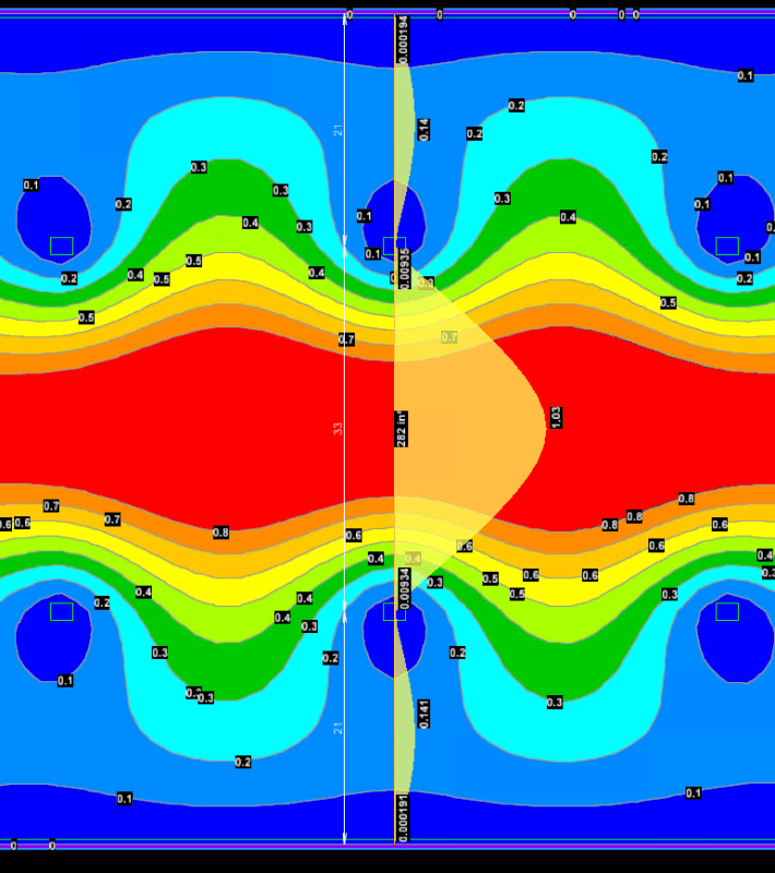
At 7-day load history with just self weight I get 1.03" of deflection:
self_delta_ifsm6r.png


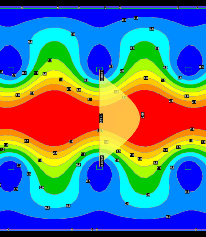
I ran several more loads steps with 2 steps being 1 day of a +125 top surface temperature + Self weight and 1 day of a -125 top surface temperature + Self weight to cover a single cycle of + and - thermal exposure.
At 6 months load history I land on 2.66" of deflection:
6months_delta_cuaend.png


I'm making a thing: (It's no Kootware and it will probably break but it's alive!)
 
"...while the interior supports are fixed columns"

This assumption is likely no longer accurate as your column bars are probably set up to be continuous into the columns above and not developed into the slab. Since the columns up don't exist yet the bars aren't tied to anything and there is no additional compression from a floor above restraining the joint.

I'm making a thing: (It's no Kootware and it will probably break but it's alive!)
 
I suspect that you need to take a much closer look at how your software is calculating deflection. Rapt is the one I would trust most on this subject....

I looked into slab deflection calculations for post tensioned slabs in great detail at one point. And, Rapt had some really good papers / descriptions on the subject. There are a number of ways to do it, some of which are described by code provisions. But, many of these are not really all that accurate.
 
Status
Not open for further replies.

Part and Inventory Search

Sponsor